
Thanks for stopping by Southeast4x4trails.com! If you are looking for a detailed guide on how to install a GMRS radio or Ham radio in your Jeep or off-road vehicle you have come to the right place. Keep reading for more details about this 5-part series on my radio install project.
If you have found your way here via Google, this site is about the Jeep, 4×4, and off-road community in the Southeast US. Check out the home page for an interactive Google map of trails, off-road parks, forest service roads, points of interest and more in the GA, TN, NC, and SC areas. The Journal has other articles similar to this one on topics of interest such as “how-to” guides, trails and places to visit, and local history. The Resources page has many links to mapping, GIS, USFS forest areas, and technical info.
This is the fourth in a series of 5 posts that detail the install of a Midland MXT400 MicroMobile GRMS radio and Icom IC-2730A ham radio in my Jeep Wrangler TJ. You can adapt this information to any vehicle, it doesn’t have to be a Jeep TJ or even a Jeep!
This post will cover the radio electrical distribution system and the installation of the maxi fuse block, 6-circuit power distribution block, Lind shutdown timer, Insultherm braided shielding and the manual override switch.
Part 1 includes a complete list of all the radio gear, tools, parts, and hardware that I used.
If you want to jump directly to the install info just click one of the links below:
- Part 1 – Project Details, Gear, Parts and Tools
- Part 2 – Mounting the Midland MXT400 GMRS Radio and Icom IC-2730A Ham Radio
- Part 3 – Mounting the Radio Antennas
- Part 4 – Power, Wiring and Fuse Block Installation
- Part 5 – Radio Power Wiring and Antenna Coaxial Cable Installation
Before we get started I’d like to ask you for a favor. If you find this post useful please consider supporting this site by purchasing any of the items listed in the post through the links provided. The links to Amazon are affiliate links, and the small commission that I may earn keeps this site running so I can continue to provide helpful information.
Parts List
The following parts were used in this post:
■ Lind SDT1230-022 Shutdown Timer – Amazon | Lind
■ I bought 2 of these in new condition on Amazon for $22.99. The retail price from Lind is $81.95.
■ Blue Sea Systems Maxi Fuse Block / In-Line Fuse Holder (5006) – Amazon
■ Blue Sea Systems ST Blade ATO/ATC Fuse Block (6 Circuit w/ Negative Stud Terminals ) (5025) – Amazon
■ Blue Sea Systems Contura II Off-(ON) SPST Switch – Amazon
■ Daystar Universal Firewall Boot (KU20040BK) – Amazon | Quadratech
■ Insultherm High Temp Braided Sleeving – 1.5″ and 5/8″ – Wire Care
■ WindyNation 8 AWG Gauge Pure Copper Flexible Cable Wire – 30 Feet, Red (Battery Positive) – Amazon
■ Windy Nation 8 AWG Gauge Pure Copper Flexible Cable Wire – 15 Feet, Black (Battery Negative) – Amazon
■ Belden 14 Gauge Primary Wire in Red, Black (25 Feet) – NAPA Auto Parts
■ Selterm Heavy Duty Bare Copper Terminals for 8 AWG Gauge Wire, #10 Ring Stud– Amazon (Qty: 6)
■ Selterm Heavy Duty Bare Copper Terminals for 8 AWG Gauge Wire, 1/4” Ring Stud – Amazon (Qty: 1)
■ NAPA Auto Parts In-Line Mini Fuse Holder (784667) – NAPA Auto Parts
■ Blue Sea Systems 30 Amp Maxi Fuse (5138) – Amazon
■ Littelfuse ATO 15 Amp Smart Glow Fuse (Qty: 2) (0AT0015.VPGLO ) – Amazon
■ Littelfuse 5 Amp Mini Fuse (0MIN005.VP) – Amazon ($3.81)
■ Dorman 16-14 Gauge Butt/Crimp Connectors (85436) – Advance Auto
■ Dorman 16-14 Gauge 1/4″ Ring Terminal (85409) – Advance Auto (Qty: 1)
■ NAPA Auto Parts 16 to 14 Gauge Step Down Butt/Crimp Connector – NAPA Auto Parts
■ Tyco Electronics Raychem #10 Spade & Ring Terminals for 16-14 Gauge Wire – Home Depot (Qty: 1)
■ MaxBrite 16-14 Gauge Fully Insulated Female Disconnect Terminals – Amazon (Qty: 2)
■ Ideal Ground Screws (774042) – Home Depot
■ Storehouse 42 Piece Marine Heat Shrink Tubing (Qty: 2) – Harbor Freight Tools
■ XHF 160 Piece Clear Heat Shrink Tubing – Amazon
■ Gardner Bender 3/8” & 1/2” Electrical Split Flex Tubing (FLX-538C10) – Home Depot
■ Gardner Bender 3.5 Foot Wire Spiral Wrap (FLX-538C10) – Home Depot
■ Gorilla Glue Heavy Duty Mounting Tape – Amazon
■ Rust-Oleum Clean Metal Flat White Primer (7780830) – Amazon
■ Rust-Oleum Flat Black Protective Enamel (7776830) – Amazon
■ Rust-Oleum Universal Dead Flat Clear Durable Topcoat (342482) – Amazon
Radio System Guide & Wiring Diagram
The graphic below shows the entire radio system and how each component is connected and wired. All parts that are in front of the ‘Jeep Firewall’ box are mounted in the engine compartment. Click to download the diagram in PDF format.
The components that are covered in this post are shown below in red.

1. Install The Maxi Fuse Block
Before your start step 1 make sure you DISCONNECT the battery terminals from the battery.
The maxi fuse block protects the radio power system against high or excess current flow if something fails. Maxi fuses are larger than your “regular size” ATO/ATC fuses, and are typically designed specifically for higher amperage vehicle electric systems.
The Blue Sea Systems 5006 Maxi Fuse Block encloses both the fuse and the connector terminals within the plastic housing. This is important because the maxi-fuse block is mounted in the Jeep engine compartment and will be exposed to the elements. This fuse block accepts maxi fuses from 30-80 amps, but a Blue Sea Systems 5138 30 amp maxi-fuse is sufficient for the radio power system.
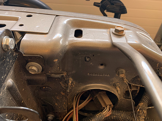
Mount the maxi fuse block on the passenger side above the headlight wiring on the inside of the front grille. This is the same side that the Jeep’s battery is located on.
Use a #10-16 x 1/2″ self-drilling screw to secure it to the body. Also, leave the terminal screws on the fuse block loose for now. You will need to attach the wire
terminals and if you tighten the screws the maxi fuse will not fully seat in position due to the tension applied by the terminal screws.
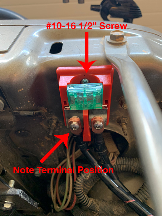
On the fuse block, the terminal on the right side will be the power from the Jeep’s battery and the left side will be the power run to the 6-circuit power distribution block inside the Jeep. Use a heavy gauge wire such as the Windy Nation 8 AWG gauge stranded wire in red (positive) for the power line from the battery to the fuse block terminal. I ordered 30 feet of the red wire and it was sufficient for the total install.
Using the wire, measure the distance from the battery positive terminal to the right terminal on the fuse block. I left a little slack and cut the wire a bit longer than it actually needed to be in case something happened when crimping the copper wire terminals on either end of the wire.
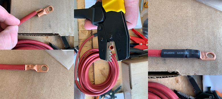
Leaving some slack also allows you to route the wire from the battery to the fuse block a bit easier as well. The terminal screws on the fuse block are #10 size. To crimp (attach) the copper terminal to the wire, strip back about 1/2″ of the exterior shielding on the wire and twist the wire strands to make sure they are wrapped together tightly. No wire strands should extend outside of the terminal when it is crimped.
On one end of the wire cut a ~1.5″ piece of 3/8″ marine heat shrink and slide it over the end of the wire. Next, attach a Selterm #10 ring stud 8 gauge heavy-duty copper terminal using a ratcheting crimping tool such as the Fryic ratchet crimping tool for 20-7 gauge wire. I found it easier to place the copper terminal in the crimping tool first, then insert the wire and crimp. The ratcheting crimping tool will make sure your crimp connection is tight around the wire. The ratchet motion allows you to create more force as compared to a fixed crimping tool creates.
However, before you crimp the connector test fit the stripped length of the wire into the terminal to make sure excess wire is not exposed outside of the end of the terminal. Ideally, just strip away enough of the shielding to fit the exposed wire into the terminal so that the wire shielding sits up against the end of the terminal. When crimping the terminal make sure you crimp the entire length. Complete one crimp, then slide the crimping tool over and complete another crimp. See the photos below for reference.
For the terminal on the other end of the wire, check the size of the post on your battery positive terminal. The post on my battery is 1/4″, so I used a Selterm 1/4″ ring stud 8 gauge heavy-duty copper terminal along with another piece of 3/8″ marine heat shrink.
Once both terminals are attached to the wire, use a heat gun to contract the heat shrink material over the copper terminal and the wire. Heat the heat shrink material until you can see a bit of the glue expand outside of the ends of the heat shrink material. The marine heat shrink material uses this “glue” type material to create a seal that is resistant to water (marine).
Do not attach the wire to the battery post and fuse block quite yet. There are a couple of additional steps to complete first.
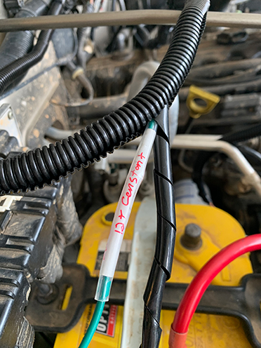
IMPORTANT – Label the red battery positive wire. It is easy to get the wires mixed up and forget which wire is which once you start routing them through the Jeep firewall and into the cabin.
For the labels, I used regular Avery 06141 file folder labels that you can buy on Amazon or at any office store. These labels have marks on each side at the center of the label. I aligned those marks with the center of the wire (as best I could). Attach the label to the wire, then slide a piece of clear heat shrink over the label and heat it up for a nice, weatherproof seal. I put ’12V+ to Maxi Fuse Block’ on the label.
After the label is attached to the wire, cover the entire length of the wire with both plastic spiral wrap and plastic split flex tube. This helps protect the wire from melting or damaged from heat since it is in the engine compartment of the Jeep. Use a plastic zip tie on each end of the wire to secure the spiral wrap and split flex tube in place. Make sure you pull the zip tie tight so the plastic tubing can not slide up and down on the wire. A zip tie puller tool helps to make sure the tie is tight and secure.
Next, repeat the same process to attach terminals to the wire that will run from the maxi fuse block, through the Jeep’s firewall and into the cabin and the Lind shutdown timer. This will provide the power to the shutdown timer, and in turn to the larger in-cabin 6-circuit fuse block.
Attach another Selterm #10 ring stud 8 gauge heavy-duty copper terminal to one end of the 8 gauge red wire along with another piece of 3/8″ marine heat shrink. Cover it with spiral wrap and split flex tube from where it attaches to the maxi fuse block terminal to where it will pass through the Jeep firewall.
Do not cut the length of the wire that will run through the firewall and into the cabin yet. That wire will be routed into the cabin first, then it can be cut to the appropriate length based on where it will connect to the terminal on the Lind shutdown timer. Once the wire is cut to that length, attach another Selterm #10 ring stud 8 gauge heavy-duty copper terminal.
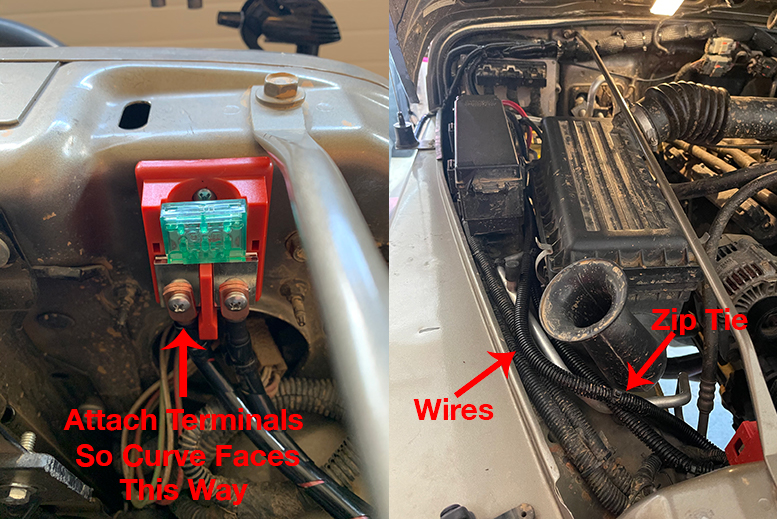
Next, attach both pieces of wire to the terminals on the maxi fuse block. Turn the terminal connectors so the curve of the connector is facing the maxi fuse block – basically connecting them “backwards” so that the curvature of the connector faces inward. The cap to the maxi fuse block will not fit if you attach the connectors the other way. See the photo below for reference.
Before you tighten the terminals screws insert the maxi fuse into the fuse block. Then tighten the terminal screws and place the cover onto the fuse block.
I routed both wires so they run from the fuse block and through the space in between the air filter box and the Jeep fuse panel. I zip-tied both of the wires together then just tucked them down into the space between the air filter box and fuse panel.
Set the wires aside near the battery for now. There are a couple of other steps before you route them through the Insultherm bradied shielding and into the cabin of the Jeep.
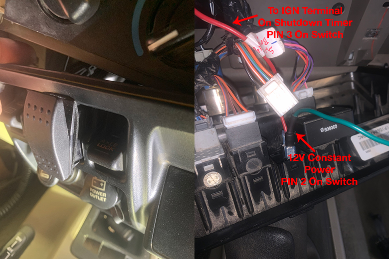
2. Run Wire For 12V Constant Power To The Manual Override Switch
The reason for the manual override switch is explained below, but the next step is to wire up a source of 12V constant power that will connect to PIN 2 on the Blue Sea SPST (single-pole, single-throw) momentary switch. This power will be supplied directly from the battery positive terminal to PIN 2 on the switch.
I tried to find a fuse/circuit on the OEM interior Jeep fuse block that supplied constant 12V power, but all of the available or open fuses were ignition switched. This means that no power is present when the Jeep ignition is in the OFF position. For the switch to operate as needed, it requires a source of 12V constant power regardless of if the Jeep ignition is switched ON or OFF.
For now, you just need to attach a ring terminal to a length of 14 gauge wire such as Belden 14 gauge primary wire. I had some 14 gauge wire in green available, but you might consider using red (wire) to indicate that it is a “hot” power wire. If you are using a new roll wire (usually 25 feet) just attach the terminal to one end of the wire, then it can be cut to the appropriate length once the wire is routed through the firewall and into the Jeep cabin and switch.
Select the appropriate size ring terminal for your battery post. I used a Dorman 16-14 gauge wire 1/4″ ring terminal. Cut a piece of 1/4″ diameter marine heat shrink and slide it over the 14 gauge wire, then measure and strip the wire shielding.
Crimp the ring terminal connector with either a ratcheting crimp tool like the IWISS ratchet crimping toolset with a 22-10 gauge wire die or a fixed-style crimp tool such as the Klien Tools 1000. Use your heat gun to contract the heat shrink material until the glue starts to run out of the ends.
Also, label the wire just as you did with the 8 gauge red power wire. I put ’12V Constant’ on the label. Cover the wire with the plastic spiral wrap and split flex tube from where the wire will connect to the battery post to where it will enter the Jeep firewall.
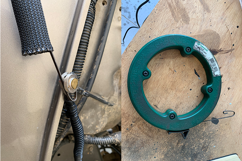
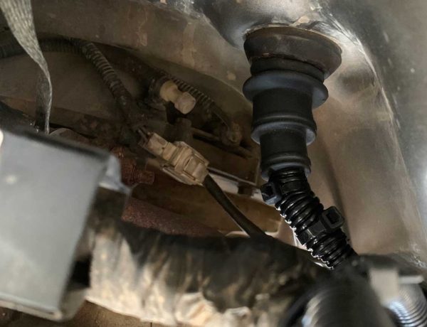
3. Install The Firewall Boot
I used a Daystar Universal Firewall Boot with a small modification to pass the wiring through the Jeep firewall. The firewall boot offers several advantages as compared to either just cutting a hole in the existing OEM firewall plug or removing it completely and passing the wiring through the factory firewall hole.
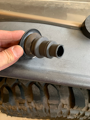
First, the boot gives a much more snug fit to hold the wiring in place. Second, it also offers protection against rain, dust or other elements from making their way into the Jeep cabin via the firewall hole.
I wrote another post on how to install the firewall boot which includes all the details and photos – How To Pass Wiring Through Your Jeep Wrangler TJ Firewall. This does only work for TJ’s with a manual transmission, however. See the post for more details about why.
I did cut off one additional section of the firewall boot to make enough room for all of the wiring to pass through the end of the boot that is in the Jeep engine compartment.
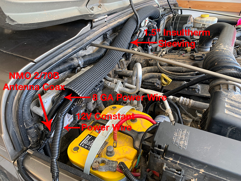
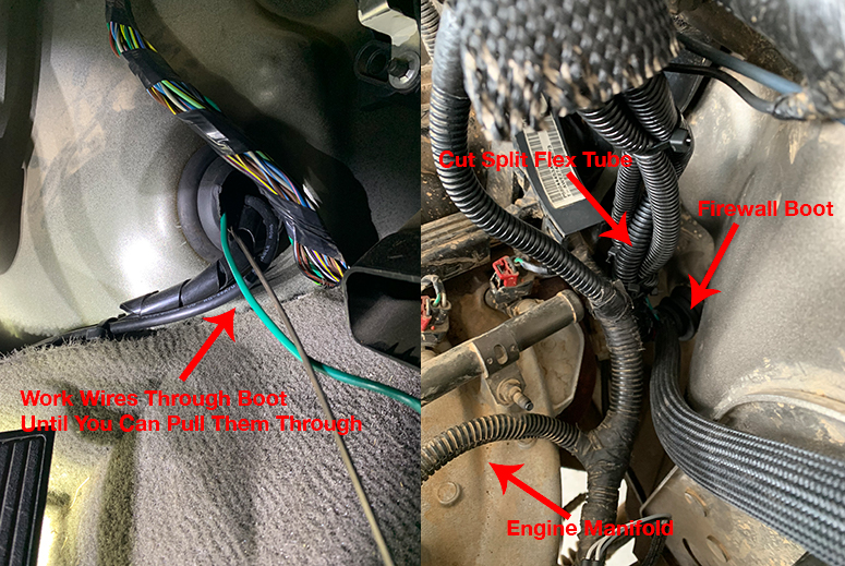
4. Route Wiring Through Insultherm Braided Sleeving
The path from the Jeep’s battery down to where the wiring will pass through the Jeep firewall runs very close to the exhaust manifold on the engine. This means that the wiring will be subject to high temperatures, and the last thing you want to do is have to re-run all the wiring again if it melts or fails due to high heat.
To protect the wiring against the heat, I used 2 sleeves of Insultherm high-temp braided sleeving. This sleeving is rated to protect up to temperatures of 1,200 degrees which is plenty sufficient for this application. I ordered a 3-foot piece of 1.5″ diameter sleeving and a 3-foot piece of 5/8″ diameter sleeving.
The following wiring will pass through the 1.5″ diameter Insultherm sleeving:
- 8 gauge red power wire for the Lind shutdown timer (from the maxi fuse block)
- 14 gauge 12V+ constant power wire for the manual override switch (from the Jeep battery)
- Antenna coax for the Larsen NMO450CHW antenna (see part 3)
- Cover the coax wire with spiral wrap and split flex tubing
The following wire will pass through the 5/8″ diameter Insultherm sleeving:
- Antenna coax for the Larsen NMO 2/70B (see part 3)
- Cover the coax wire with spiral wrap and split flex tubing
Start with the larger 1.5″ diameter sleeving. Pass the 3 wires listed above through the sleeving and towards the hole in the Jeep firewall.
Next, route the antenna coax for the Larsen NMO 2/70B antenna through the 5/8″ piece of Insultherm sleeving.
To pass the antenna coax through the Insultherm sleeving I detached the NMO mount from the mounting brackets on the front fenders. I used an electrician’s wire fish tape tool and attached the curved end of the fish tool around the NMO mount as shown below. I then pulled the antenna coax through the sleeving and re-attached the NMO mount to the mounting bracket. This will leave the bare (no connector yet) end of the antenna coax wire ready to pass through the firewall boot.
5. Pass Wiring Through Firewall Boot
Unfortunately, there is not really an “easy” way to pass all of the wiring through the firewall boot. First, I figured out where I could cut the split flex tubing on each wire so that the tubing stopped at the point where the wire entered the firewall boot. This leaves just the wire and spiral wrap to pass through the boot and into the Jeep cabin.
Next, I worked one wire at a time through the firewall boot. Hold the boot with one hand and work each wire through until you can grab it with something (either your hand or a pair of needle-nose pliers) and pull it through the boot and into the cabin. You will have to work each wire through slowly until you are able to grab it. I tried to use the wire fish tape tool to pull the wiring through the boot put given the available space in the boot it didn’t really work well at all.
Pass all 4 wires through the firewall boot and pull the slack through into the cabin. We will come back in a later step and secure the Insultherm sleeving in the engine bay. You may need some extra slack or to cut a wire to a shorter length once it is attached to its endpoint/component.
6. Mount The Lind Shutdown Timer
The Lind shutdown timer solves a couple of issues that I encountered when I first installed the radio system. Initially, I installed a 4-pin relay and a DPDT (double-pole, double-throw) switch that had to be in an ON position to supply power to the radio system.
About a week after I finished the install I went to start the Jeep one day and the battery was dead. The DPDT switch had a light that was always on, so I suspect it slowly drained the battery. I charged the battery up once and it slowly discharged again, so I removed the relay and DPDT switch.
The Lind shutdown timer is designed to turn off after a preset amount of time once the Jeep engine is shut down. This kills all power to the radio system once the preset amount of time is reached. I set the timer to turn off 30 minutes after the Jeep engine is turned off. The timer also has a built-in relay to handle power switching.
You can use the SPST (single pole, single throw) manual override switch in the Jeep cabin to tell the timer to turn on again even when the Jeep engine is shut down. This allows you to operate the radio system if you need to when the Jeep isn’t running.
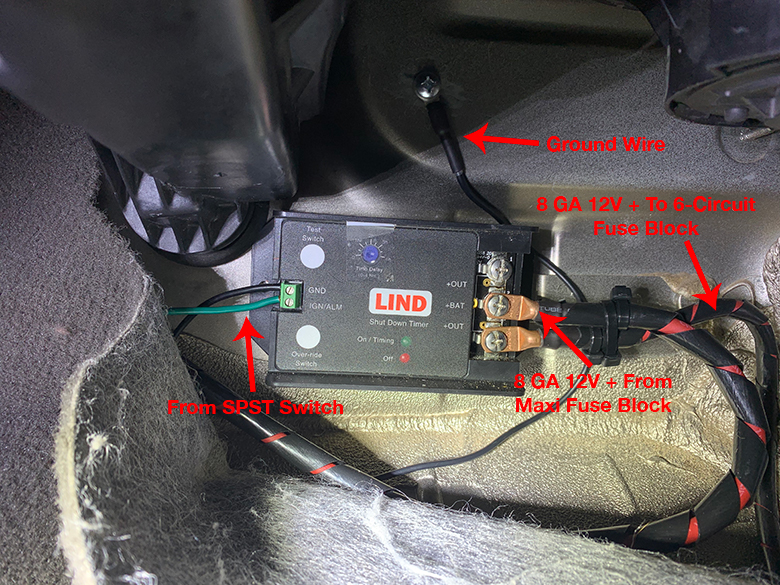
As outlined in the wiring diagram at the top of the page, the 12V power to the timer comes from the maxi fuse block and connects to the +BAT terminal on the timer. One of the +OUT terminals on the timer supplies the 12V power to the larger Blue Sea 6-circuit fuse block. The GND terminal on the timer is grounded to the Jeep battery, and PIN 3 (LOAD) on the SPST manual override switch runs to the IGN terminal on the timer.
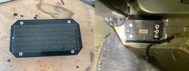
I mounted the shutdown timer on the passenger side firewall underneath the carpet on the floorboard. Use two pieces of Gorilla Glue heavy-duty mounting tape (it’s rated to hold up to 30 pounds) as shown above. Stick the timer to the firewall and firmly hold it in place for 1-2 minutes so the mounting tape bonds to the firewall. This much easier than trying to attach the timer to the firewall with screws. The +OUT and +BAT terminals on the timer should be facing the passenger side of the Jeep.
It is much easier to mount the timer if you remove the passenger seat. Use a T50 Torx bit to remove the bolts on the passenger seat frame.
7. Attach the 8 Gauge 12V Power Wire To The Shutdown Timer
Now that you have routed all of the wires through the Jeep firewall pass the red 8 gauge power wire behind the dash and over to the passenger slide floorboard where the timer is mounted. Determine where you can cut the wire and attach it to the +BAT terminal on the timer.
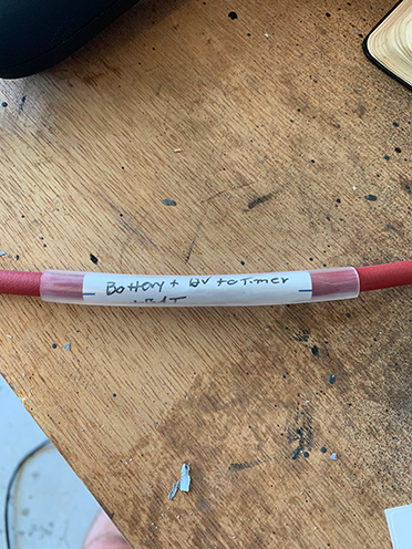
I left a little slack in the wire in case it was needed and also added some plastic spiral wrap since wire will contact the floorboard of the Jeep (it gets hot!).
Once you make the cut, label the wire as well. I put ‘Battery + 12V to Timer +BAT’ on the label.
Use a #10 Selterm heavy-duty copper terminal and a piece of 3/8″ marine heat shrink just as you did in step 1 and secure it in place with the screw on the +BAT terminal on the timer.
8. Wire the Shutdown Timer Ground
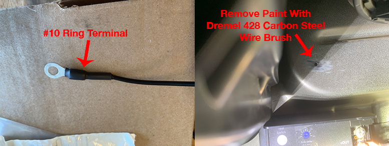
To ground the shutdown timer, use a piece of 14 gauge primary wire, preferably in black to represent that it is a ground wire. Cut and slide a piece of 1/4″ marine heat shrink onto the wire, then attach a #10 ring terminal for 16-14 gauge wire to one of the wire with either a rachet or fixed crimping tool. Apply heat to the heat shrink until it contracts the glue runs out of the end of the tubing.
To create a proper ground connection remove a bit of the paint from the area where you will attach the wire to the Jeep body. I attached the wire just above the shutdown timer (see photo below). A Dremel 428 carbon steel wire brush makes removing the paint nice and easy. You only need to remove just enough so the ring terminal makes contact with the bare metal on the firewall.
To attach the wire to the firewall drill a small pilot hole first, then secure it with a #12-3/4″ self drilling screw. On the opposite end of the ground wire, strip a small portion of the shielding back and attach the wire to the GRD terminal on the timer by loosening the screw in the terminal, insert the wire into the terminal opening, and re-tighten the screw.
All of the wires are attached to the timer in the photo below. This includes both the 8 gauge power wire that will run to the 6-circuit fuse block and the wire from the SPST manual override switch.
9. Wire The Manual Override Switch
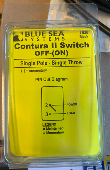
I used a Blue Sea Systems 7930 Contura II SPST Momentary switch for the manual override. “Momentary” means that when the switch is in the ON position, it is only there for a moment. You push the switch to the ON position, then it returns to the OFF position. When the switch is pressed, it tells the Lind shutdown timer to turn on and supply power to the 6-circuit fuse block so the radios can be operated. A non-momentary switch stays in the ON position until it is pressed again to return to the OFF position.
The notation on the package (ON) means that the ON position is momentary. The 12V constant power wire from step 2 connects to PIN 2 (POWER) on the switch and PIN 3 (LOAD) is wired to the IGN terminal on the Lind shutdown timer.
Route the 14 gauge 12V constant wire behind the dash and into the glove box compartment (remove the glove box for easy access). Since the wire is constantly powered a fuse needs to be installed to protect the circuit. I used a NAPA Auto Parts Inline Mini Fuse Holder which has 16 gauge wire. NAPA also makes a 16 to 14 gauge step-down butt/crimp connector, so use one of those and attach the 14 gauge end of the connector to the 14 gauge 12V constant power wire.
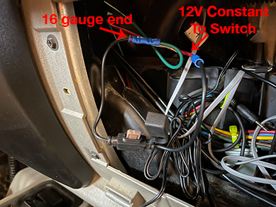
Connect the 16 gauge end (this end is marked by the black band on the connect, see in the photo above) to the inline fuse holder. On the other end of the inline fuse holder, crimp the 16 gauge end of another step-down butt connector to the fuse holder. Cut another length of 14 gauge wire that will run to the switch (red in the photo above), and connect it to the 14 gauge end of the butt connector. You can use marine heat shrink on these connections as well.
Insert a Littlefuse Mini 2 Amp Fuse into the fuse holder and place the fuse holder in a secure place within the glove box.
The switch will fit in the factory Jeep TJ switch pod. Remove the center dash bezel and the switch pod and place the switch into one of the open holes. When the switch is seated in the holder it will look like the photo below.
Cut a length of 14 gauge primary wire to run from PIN 3 on the switch to the IGN terminal on the shutdown timer. Attach 2 16-14 gauge female disconnect crimp terminals to the 12V constant wire and the IGN wire along with marine heat shrink on each wire. Seat the female disconnect terminals onto their respective switch pins and re-attach the switch pod and the center dash bezel. Label both of the wires as well.
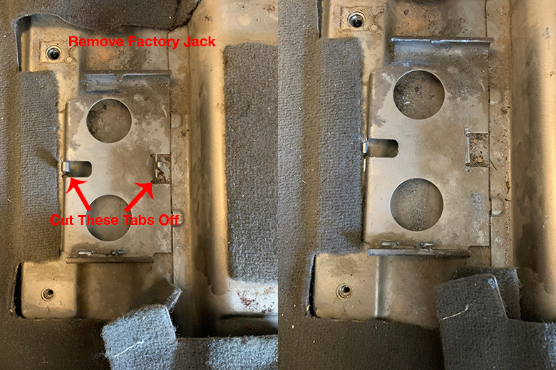
10. Mount The 6-Circuit Fuse Block
The radio power leads connect to the Blue Sea Systems 5025 ST Blade ATO/ATC fuse block. Using this type of fuse block allows you to run one source of power from the battery to the fuse block, and power multiple devices from the fuse block instead of running individual power leads for each device (to the Jeep battery). The fuse block I used allows you to attach up to 6 circuits/devices.
Mount the fuse block under the passenger seat (leave it out of the Jeep until the install is finished). You will need to remove the factory jack that comes with the Jeep and cut off the 2 mounting tabs for the jack so the fuse block will fit in this space.
Use a pair of pliers to bend the tabs over into a position where they can be cut off. I used a Ryobi 9340 rotary tool and a Dremel MM485 carbide flush cut oscillating (rotary) blade to make the cuts.
Next, cut a piece of 3/4″ plywood to a dimension of 7.5″ (long) x 4.5″ (wide). The fuse block will be mounted to the plywood, and the plywood is attached to the Jeep body. Test fit the piece of plywood in the mounting location once the cuts are made.
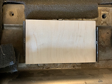
Paint the plywood black by applying 3 coats of Rust-Oleum Clean Metal Flat White Primer, Rust-Oleum Flat Black Protective Enamel and Rust-Oleum Universal Dead Flat Clear Durable Topcoat. Let the paint dry for at least 1-2 hours. I let it dry overnight before I attached the fuse block to the plywood.
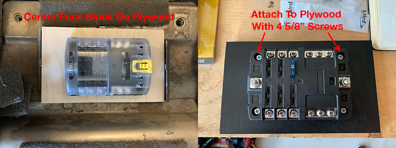
Once the paint is dry, place the fuse block onto the plywood and center it.
Mark the locations of the mounting holes with a marker or something pointed such as a drill bit. Attach the fuse block to the plywood with 4 5/8″ screws and place the fuse block in the mounting location. Do not screw it to the Jeep body yet in case you need to make any adjustments while running the radio power lead (covered in part 5 of this post series).
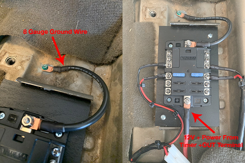
11. Run 8 Gauge Power Wire & Ground Wire to Fuse Block
Attach a Selterm 8 gauge #10 heavy-duty copper terminal to a piece of red 8 gauge wire with a piece of marine heat shrink. Label the wire ’12V Power From Timer +OUT’ and place a piece of clear heat shrink over the label. Attach the wire to the +OUT terminal on the Lind shutdown timer and the + (positive) terminal on the right side of the fuse block. Cover the wire in spiral wrap as well since it will sit on the floor of the Jeep body.
Next, cut a length of about 7″ of 8 gauge black wire and attach a Selterm 8 gauge #10 heavy-duty copper terminal to both ends of the wire. Attach one end of the wire to the – (negative) terminal on the left of the fuse block. Remove some of the paint on the Jeep body with a Dremel 428 Carbon Steel Wire Brush and drill a hole for the Ideal #10-32 self-tapping ground screw. Attach the other end of the wire to the Jeep body with the ground screw.
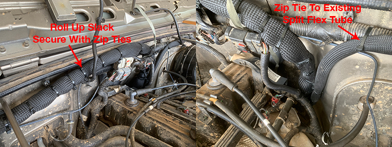
12. Secure The Insultherm Sleeving
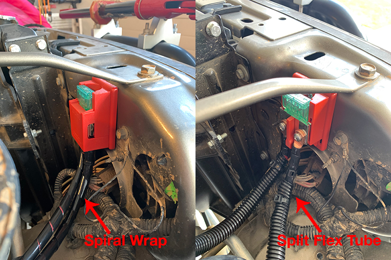
You are almost done! Now that all of the components and wiring are installed for the power system, secure the Insultherm sleeving in place with zip ties in the Jeep engine compartment.
On the 1.5″ diameter Insultherm sleeving fold any excess slack in the sleeving over (“roll it up”) and place zip ties around it to keep the sleeving and wires tight. Do this along the entire length of the sleeving. Do the same thing for the 5/8″ sleeving as well.
Secure both pieces of Insultherm sleeving to the the existing Jeep wiring split flex tube as shown in the photos below.
Up Next – Part 5
Part 5 in this series the last step of the install! It will cover the radio RF grounds, running the radio power leads to the 6-circuit fuse block, installing the PL-259 connectors on the antenna coax wires, and how to do an SWR meter test. Check it out next!
No Comments