
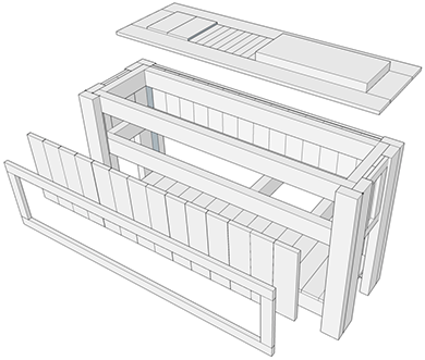
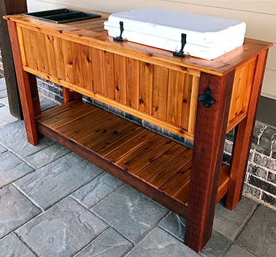
Springtime is coming! As the weather warms up now is a great time to build your own DIY wooden patio cooler stand out of cedar and custom made for a Yeti Tundra 45 cooler! This how-to post includes detailed step-by-step instructions and over 50 photos to show you exactly what to do. You can purchase the plan set to go with the post below as well. Each piece in the plan set corresponds to the steps this post.
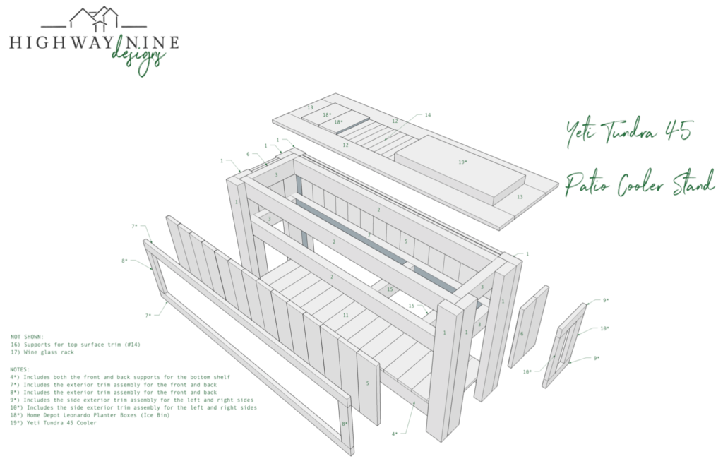
The downloadable plan set includes a 7-page PDF with a complete parts cut list and exploded, front, side, top, and top interior views. It follows this post exactly and includes all dimensions and measurements you need to build the cooler stand for only $9.99! Purchasing the plan set is risk-free. If you have any problems with your order and I will refund the entire purchase price. Just send me an e-mail and let me know why.
Click here or on the image below to download a preview of the full plan set.
The version you receive will include all measurements and dimensions.
Materials
Total Material Cost: $320 (as of the time of build)
The total material cost assumes you have all of the required tools and a Yeti Tundra 45 cooler (or another cooler that you plan to use).
Before we get started I’d like to ask you for a favor. If you find this post useful please consider supporting this site by purchasing any of the items listed in the post through the links provided. The links to Amazon are affiliate links, and the small commission that I may earn keeps this site running so I can continue to provide helpful information.
Cedar Lumber
- 2″ x 4″ Western Red Cedar (8 boards @ 8 feet)
- 1″ x 6″ Cedar Trim (2 boards @ 8 feet)
- 1″ x 4″ Cedar Trim (10 boards @ 8 feet)
- 1″ x 2″ Cedar Trim (5 boards @ 8 feet)
Nails & Fastners
- 2.5″ Kreg Pocket Hole Screws (I purchased 3 boxes and ended up using about 2.5 boxes worth of screws.)
- 1 1/4″ 18-Gauge Brad Nails or Finish Nails (1 box of either brad nails or finish nails is plenty)
- #8 1 1/4″ Exterior Screws (For the top service area trim support and wine rack)
- Wood Glue
Containers For Ice Bin
- Home Depot Leonardo Plastic Plant Window Box (2 boxes)
- These boxes are used for the ice bins for wine bottles. The dimensions of the planter box fits the stand perfectly!
Wood Stain / Urethane
- PPG/Sikkens ProLux Cetol Log & Siding – Cedar 077 (SIK42077, 1 gallon)
- This is a high-end stain that was recommended by my local custom home store. It seals the wood very well to protect it against the outdoor elements. You can use another stain that is a bit more budget-friendly such as Minwax Helmsman Indoor/Outdoor Spar Urethane. I do recommend spending the money on a high-quality stain/urethane to help the stand last as long as possible outdoors
- It takes about a 1/2 gallon to apply 2 coats to the entire stand
Cooler
- Yeti Tundra 45 Cooler
- I already had the 45 model cooler, so I built the stand specifically to fit it. If you don’t have this model Yeti cooler (or don’t want to spend $299 on it), just adjust the width dimensions on the plans to fit the outside-to-outside width of the cooler you already have or want to use
- If you don’t know the dimensions of your cooler, try searching the manufacturer’s website and look for a specifications page, such as this one published by Yeti
Tools
- Miter Saw
- I use a Dewalt 12″ sliding compound miter saw. The Ryobi 10″ sliding compound miter saw or the Ryobi 10″ compound (non-sliding) miter saw are perfect for this project as well
- Table Saw or Circular Saw
- The table saw is used to trim the top trim pieces to a width of 4″. You can make this cut with a circular saw as well. If you use a circular saw consider also using a straight edge system to make sure the cuts are straight and accurate. I have the Rockler system and once you learn how to get it set up correctly it makes perfect cuts every time
- Impact Driver (optional)
- Optional, but makes driving the Kreg pocket hole screws much easier. An impact driver provides much more torque than a regular electric drill, which makes it easier to drive the screw into the wood to the full depth
- Electric Drill
- Jigsaw
- The jigsaw is used to cut the end trim pieces on the front, back and sides. There is more detail below on why these need to be cut
- 18-Gauge Finish Nailer / Nail Gun
- Kreg Pocket Hole Jig
- If you don’t already have a Kreg pocket hole jig, strongly consider purchasing the K4 pocket-hole system. It includes everything you need to get up and running to create pocket holes and it’s very simple to use
- Kreg 3″ Pocket Hole Driver Bit
- Palm Router or Router
- The Bosch Colt 1-HP Variable Speed Palm Router is ideal for this project. It’s compact and easy to operate with one hand, which makes routing the edges of the trim pieces quick and easy
- 45 Degree Chamfer Router Bit
- If you use the smaller palm router make sure the router bit is the proper size to fit in the router. The first bit I purchased was too large to fit, so I ended up using the Irwin 1 19/64″ carbide-tipped chamfer bit from Lowes. The larger 1 3/4″ Diablo 45-degree bit from Home Depot should work fine in a full-size router
- 1/4″ Rabbet Router Bit (optional)
- This bit is used to cut the groove for the wine racks, which is optional. Ryobi sells a 15-bit router set that includes both 1/4″ and 1/2″ rabbeting bits. The 1/4″ bit is perfect for the wine rack. You can also find a single bit that is capable of cutting multiple rabbet depths such as the Freud model available on Amazon
- Laser Distance Measure (optional)
- This tool is optional, but it makes measuring difficult to reach areas much easier
- Tape Measure
- I prefer this style of tape measure that has fractional measurements
- Rafter/Speed Square or 90-Degree Carpenter’s Square
- 24″ I-Beam Level
- The 24″ length is a good all-around size for a level, but you could use a longer or shorter one if you already have it on hand
- Torpedo Level
- Trigger Clamps
- I used about 6 clamps throughout the project. These are used to clamp the material together after gluing to ensure a strong bond
- Counter Sink Drill Bits (optional)
- These bits allow the outdoor screws (used to attach the top trim supports) to sit flush with the exterior surface of the wood
Nominal vs. Actual Lumber Dimensions
It’s important to understand the difference between “nominal” lumber dimensions and “actual” lumber dimensions. Basically, the idea is that a 2″ x 4″ board doesn’t actually measure 2″ x 4″. The actual width and thickness are less than 2″ and 4″.
Nominal Dimension – The “trade name” or “identification” size, such as 2″ x 4″. Nominal dimension is simply used as just a reference to a common board size
Actual Dimension – The actual size of the lumber. For example, a 2″ x 4″ actually measures 1.5″ x 3.5″
The reason that knowing the difference between nominal and actual lumber dimensions is important is because it will affect the outcome of your project. If you just assume that the nominal dimension is the actual dimension, you will end up with incorrect measurements and pieces that do not fit together properly.
If your project isn’t coming together correctly and the measurements are off, this is one of the first things to consider. Take a look at the Kreg Tool article on Nominal vs. Actual Sizing for more details and a nice illustration.
The actual dimensions of the cedar wood used in this project are a bit different than the standard nominal dimensions. Here are the actual dimensions for the 4 board sizes used for the patio cooler:
- 2″ x 4″ (nominal) / 1.75″ x 3.75″ (actual)
- 1″ x 6″ (nominal) / 5/8″ x 5.5″ (actual)
- 1″ x 4″ (nominal) / 3/4″ x 3.5″ (actual)
- 1″ x 2″ (nominal) / 3/4″ x 1.5″ (actual)
Cut List
The plan set PDF includes a complete cut list of all of the pieces and is on page 2.
This list will give you a better idea of how many different pieces there are in the overall project.
I will say this about cutting all the pieces prior to assembling them – I virtually never pre-cut all the pieces. Why? I like to cut the pieces for each step individually in case any adjustments need to be made to the dimensions of a given piece.
Let’s be honest, woodworking isn’t always an exact science despite our best intentions. Cutting the pieces as you progress through the project helps minimize material waste and allows for on-the-fly adjustments. It may take a little more time, but it often leads to less frustration.
Step 1 – Stand Legs
(PART #1 IN PLAN SET)
The legs of the cooler stand are made out of the 2″ x 4″ cedar board. Each leg requires 2 boards.
It is very important that all the legs are the same length. This is also true for the rest of the components as well. If the lengths of the difference pieces are off by as little as 3/16″ to 1/4″ it can throw the overall dimensions off and result in issues such as pieces not fitting together properly.
TIP: CUT 1 LEG AND USE IT AS A GUIDE
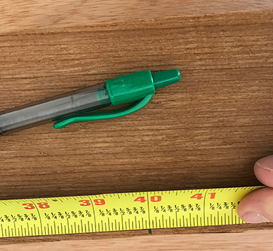
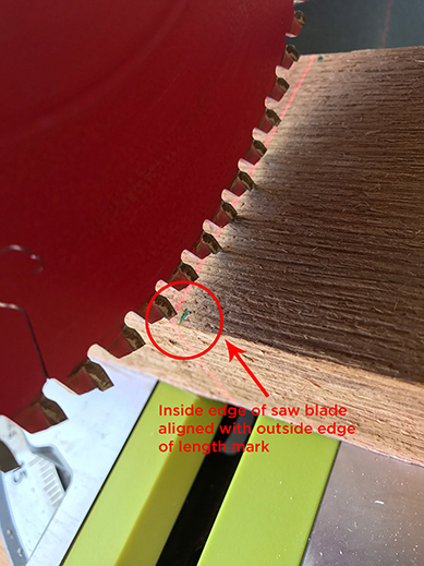
Measure the length of the leg and mark it with your pencil. I like to use a green pen as it’s easier to see in the shop and makes a line that is thick enough to see, but not so thick that it makes it more difficult to know where to place the saw blade when making the cut.
Place the board on the miter saw, and bring the saw blade down close to the board so you can see where the saw blade will contact the board. Adjust the position of the board so that the saw blade will make the cut on the outside of your length mark. Take into account the width of the saw blade. If you place the blade to the inside of your length mark your cut will come up about 1/8″ short. If your miter saw has a laser use it to help align the blade, but don’t always trust that the laser is dead accurate. It’s better to cut the board a little long and trim it slightly until it’s just the right length than cut it short.
NOTE: If you have a sliding miter saw place the length mark on the end of the board closest to you when standing at the saw. This makes the cut easier to align vs. placing the mark on the end of the board that is closest to the saw fence. If your miter saw isn’t a sliding model, place the mark on the edge closest to the saw fence.
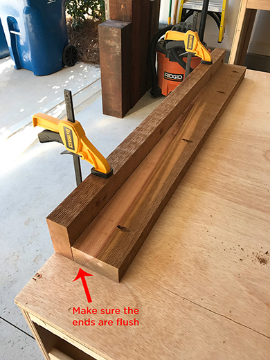
Double-check to make sure that your cut is exactly equal to the length of the leg. Use the first leg as a guide to cut the remaining 7 pieces. Place the remaining length of the board on the miter saw deck, then take the leg you just cut and set it on top of the board. Align the end of the (already cut) cut leg with the end of the board on the saw and make sure they are flush.
Slide both boards forward on the saw until they are close to the saw blade. Bring the saw blade down, and set the position of the board to where the inside edge of the saw blade barely clears the cut leg. This will ensure that the legs are exactly the same length. Repeat this process using the first leg cut until you have cut 8 total pieces.
This video demonstrates the cutting process:
Once all 8 legs are cut, lay them out on a level, flat surface and check to make sure that all legs are the same length. If any of the legs are too long use the miter saw to trim them down a “blade width” at a time. This means just trim the board by the width of the miter saw blade (about 1/16 – 1/8″) incrementally until the leg is the correct length.
Step 2 – Drill Pocket Holes On Stand Legs
Pocket holes are a simple way to add both a professional touch and functional strength to your projects. The pocket holes allow you to hide the screws that join the pieces of the cooler stand together while creating a very tight joint between the two boards. I use Kreg’s K4 pocket-hole jig system. If you haven’t used pocket holes in your projects before don’t worry, it’s very easy to learn how the jig system works and to get up and running fast.
TIP: ORIENTATION MATTERS. LAY THE LEGS OUT FIRST AND MARK THE HOLES BEFORE DRILLING
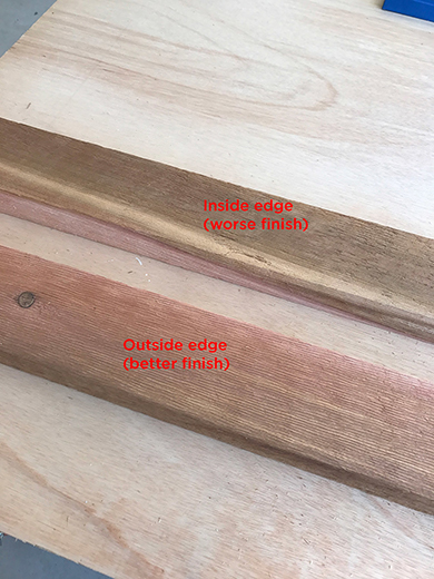
Take two of the legs and lay them out as if you were assembling them. Take a look at both sides of each board – which side looks the best? That side will be the outside edge of the leg. The pocket holes will be on the opposite side, which is the inside edge. Keep this in mind as you drill the pocket holes.
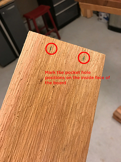
Once you determine which board faces should be facing outside, make a mark on the leg to indicate the outside edges as shown below.
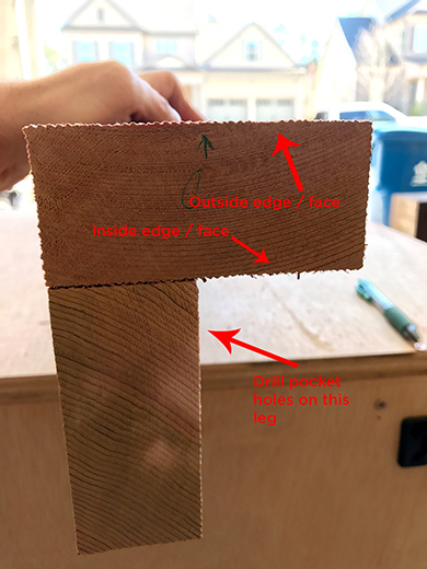
Once all of the outside edges are marked on each leg, the next step is to mark the inside edges to indicate where the pocket holes should be drilled. When you stand the legs upright you will have a “front” and “back” edge on the leg where the pocket holes will be drilled.
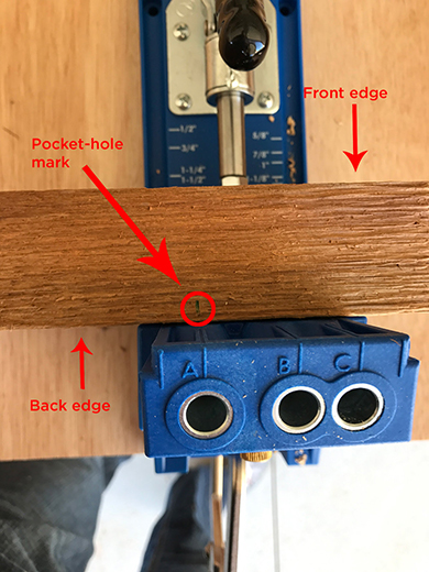
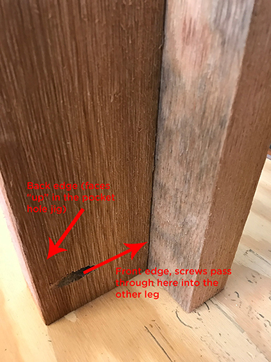
Place the legs (that you will drill the pocket holes in) upright so that the narrow end is facing upward. This is the “back” edge of the leg. Place a mark at 3″, 16″, 29″ & 37″ to space out the pocket holes evenly. These marks will be used to align the leg within the pocket hole jig.
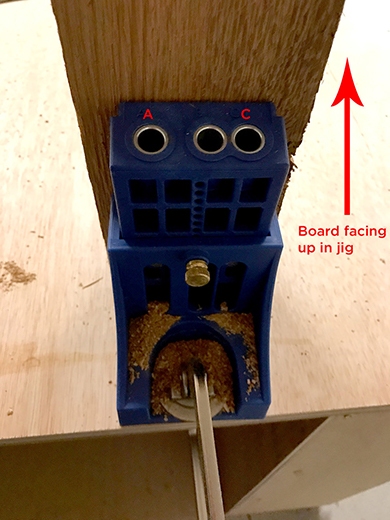
NOTE: The mark will be at the opposite end of the board in relation to where the pocket holes are drilled. The holes will be closer to the “back” edge of the leg, and the screws will pass through the “front” edge into the “inside” edge of the adjoining leg.
Place each leg into the pocket-hole jig and slide the mark for the hole to where it is aligned with the “A” mark on the jig. Support the end of the leg with a scrap piece of wood so that the leg sits level in the jig. The clamp on the pocket-hole jig will contact the “outside” edge of the leg.
If none of the above makes sense these photos should help you understand how the pocket holes work:
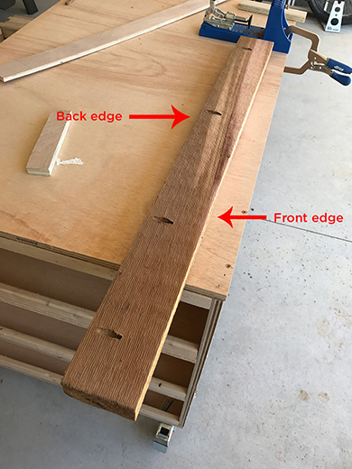
Once all 4 pocket holes are drilled the leg will look like this:
Step 3 – Assemble The Legs
You will need 2.5″ Kreg pocket hole screws, wood glue, and clamps to join the leg pieces together. Before you drive any screws, lay the legs out standing upright to make sure the orientation is correct. If you have an impact driver tool it will make driving the screws into the wood easier as compared with driving them with an electric drill. Either will work, but you may have to take a make more than one passes at driving the screw if you’re using an electric drill.
NOTE: The legs that have the pocket holes will always be on the “short” (left and right) sides of the cooler frame, not the long sides (front and back).
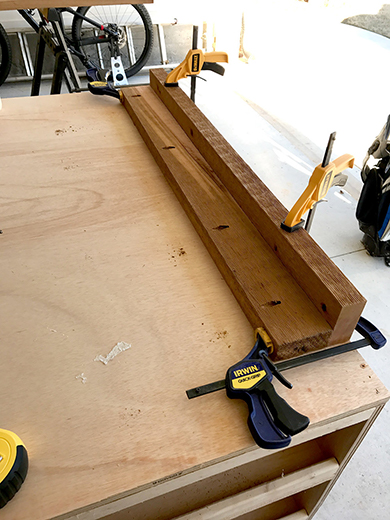
Lay the piece of the leg without pocket holes on a flat surface and clamp it down. This will hold the leg steady while driving the pocket hole screws. Run a line of wood glue along the inside edge of the leg with the pocket holes and slide it flush against the leg that is clamped down.
Make sure that both ends of the leg with the pocket holes are even with the ends of the clamped leg. Once they are, drive the pocket hole screws and add two more clamps to the ends of the leg as shown below. This will help the wood glue bond the two legs together. Let the wood glue dry overnight, or at least as long as the glue directions suggest. Assemble all 4 legs.
Step 4 – Cut The Frame Top Supports
(PART #2 IN PLAN SET)
The top frame supports join the two legs together. For now, just cut the 2 top frame supports. The bottom 2 frame supports will be cut in step 9.
Measure and mark the length of the support on a 2″ x 4″ board. Use the first support that you cut as a guide for the second support, just as you did when cutting the legs. Once cut lay the two pieces on top of each other, make sure the ends are flush, and check to make sure that the pieces are the exact same length. Trim any excess length as needed.
Step 5 – Drill Pocket Holes On Frame Top Supports
The pocket holes for the frame top supports are drilled on the “short” end of the board instead of the “long” end.
Determine which side of the board should face out and place two marks on the inside edge of the top support pieces to indicate where the pocket holes should be drilled. Place the top support piece upright in the Kreg jig and drill two pocket holes in the “A” and “C” positions. Drill 2 pocket holes on each end of both top support pieces.
Step 6 – Attach The Top Supports To The Frame Legs
(PARTS #1 & #2 IN THE PLAN SET)
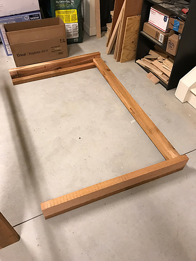
Clear out an area on the ground that is at least 6 feet wide, preferably as level as possible. Lay the legs for the front of the cooler frame on the ground with the outside edges of the legs facing the ground.
Place one of the top support pieces on top of the legs, with the pocket holes on the top support piece facing up towards the ceiling.
Test fit the pieces to make sure that the top edge of the frame top support is flush with the inside edge of the leg and that it is fully seated against the inside edge. Once you have checked the fit, add a line of wood glue to the outside edge of the top support piece where it joins with the leg.
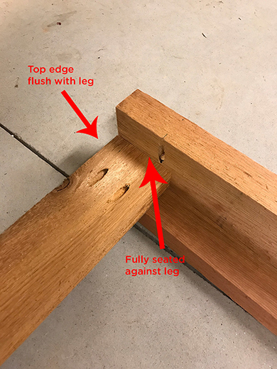
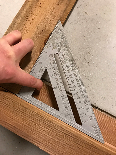
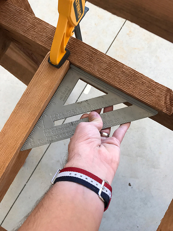
Use a rafter/speed square or a 90-degree carpenter’s square to make sure that the angle between the frame top support and the leg is 90 degrees. It is important to make sure that the angle is true to 90 degrees. If the angle is off it will make it more difficult to fit the bottom frame supports and the supports for the bottom shelf properly. It can also cause the stand to not sit level on the ground.
Basically, the width between the stand legs and the bottom will be more narrow or wide than the width at the top.
After you have verified that the angle is correct, drive the pocket hole screws. Either place your body weight on the top support as close to the leg as possible to keep it from moving while you drive the pocket hole screws, or have your partner hold the two pieces in place.
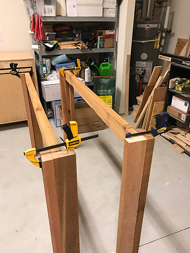
Once the pocket hole screws are in place, stand the leg assemblies upright and place a clamp on each end and let the wood glue dry overnight.
Step 7 – Cut The Top Frame Side Supports
(PART #3 IN PLAN SET)
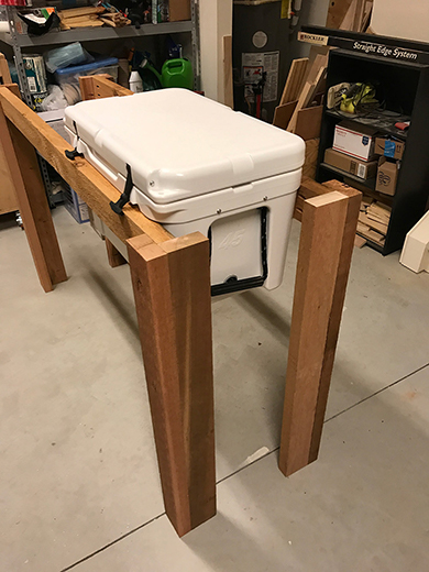
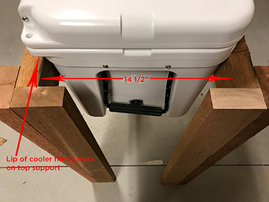
The frame side supports join the front and rear leg assemblies together to form the full “rectangular” frame. They also determine the interior width of the stand, which is important because the interior width needs to be just wide enough to hold the cooler but still provide enough surface for the “lip” of the Yeti cooler to rest upon. The Yeti Tundra 45 is designed so that the lower 3/4 of the cooler is narrower than the top 1/4. This difference in width provides a recessed lip that will sit on the top trim of the cooler stand.
Set your cooler in the stand as shown to the right and adjust the width of the leg assemblies so that the cooler sits firmly in between the front and back leg assemblies. Measure the distance between the inside edge of the front leg assembly and the inside edge of the rear leg assembly. The distance should be 14 1/2″ to 14 3/8″ for the Tundra 45 model (the plans specify 14 1/2″ for the side support piece, but double-check this measurement before you cut the side supports). If you are using a different cooler model just adjust the width of the leg assemblies accordingly to match the width of your cooler.
Once you have verified the interior width dimension mark this on a 2″ x 4″ board and cut the first side support. Test fit the support piece in between the front and back leg assemblies, and trim the side support piece as necessary.
It helps to have someone hold the stand leg assemblies upright when test fitting the side support pieces so that the entire thing doesn’t fall over. Cut 3 more side support pieces to the exact same width using the same method as the stand legs. It is very important that the side supports are the exact same length. If they are not the same, the bottom portion of the stand will likely be narrower in width by 1/4″ to 1/2″ inches which
means that the pieces for the top side of the bottom shelf will need to be different lengths (see part #11 in the plan set). Measure twice, cut once. Determine which face of the top support should face outwards and place two marks on the interior face of the side support pieces for the pocket holes.
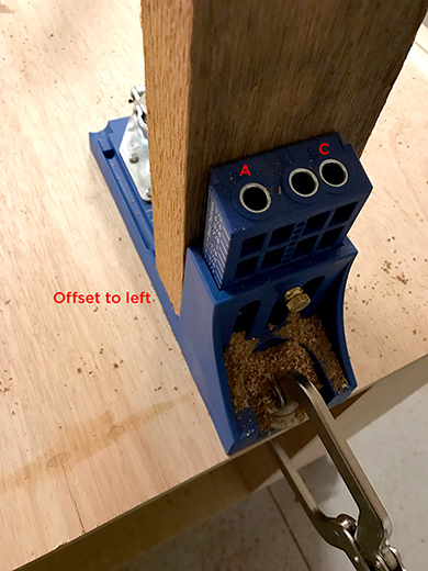
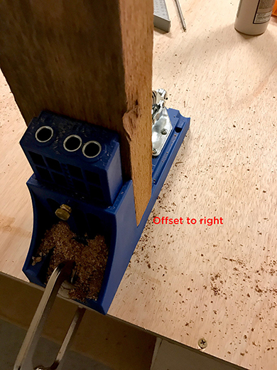
You will want to offset the pocket holes slightly on the side supports to make sure that the pocket hole screws don’t hit the screws that attach the top supports to the legs. When you place the side support pieces in the Kreg jig just offset the board to the right and left sides, then drill the pocket holes at positions “A” and “C”.
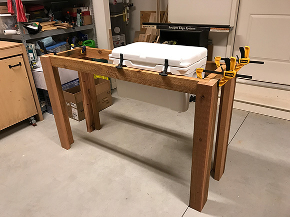
Place a line of wood glue on the outside edges of the side supports and make sure they sit flush with the inside edges of the front and back frame leg assemblies. Use your speed square or 90-degree carpenter’s square to make sure that the angle between the side support and the front or back leg assemblies is 90 degrees (again, just as important as in step 6). Drive the pocket hole screws, apply clamps to each end and let the wood glue dry overnight.
Step 8 – Cut & Install Top Trim Pieces
(PARTS #12 & #13 IN PLAN SET)
This step may seem out of order – why cut the top trim pieces before you cut the bottom frame supports? The reason is that the trim that sits on the top side of the cooler stand adds 3/4″ an inch of height. The top trim pieces need to be in place so you can set the cooler in the stand and get the correct measurements for the bottom frame supports and the cooler supports (see part #15 in the plan set). If you take the measurements without the top trim in place your bottom frame supports and the cooler supports will be off by about 3/4″.
The 1″ x 6″ board is used for the top trim pieces, but cut down to a narrower width of 4″. Since the actual width of the 1″ x 6″ board is 5.5″, you will need to trim 1.5″ off of the board. You can use a table saw or a circular saw to make these cuts.
If you are using a circular saw, consider using a straight edge system to make sure your cuts are straight. You can also make a straight edge out of any scrap board you have that you are sure is square and straight. If you are using a circular saw and a straight edge, first mark the board at 4″ and then hold your circular saw up to the mark so that the outside edge of the circular saw blade is positioned at the outside edge of the mark. Take your pen or pencil and mark the edge of the circular saw deck, then align your straight edge against that mark and clamp it in place. This will position the circular saw blade in exactly the right spot for the cut.
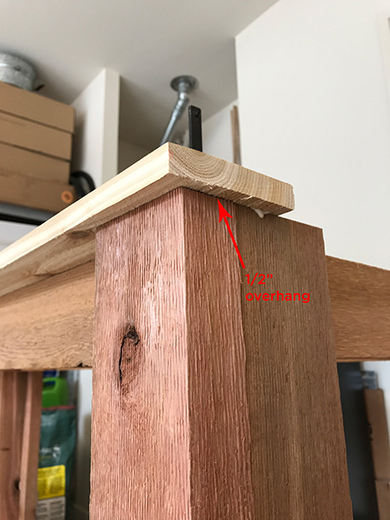
The overall width of the stand from the outside of the left leg to the outside of the right leg is 64″. To give the front and back top trim pieces about a 1/2″ of overhang, cut the length of the front top trim piece to 65″ (see part 12 in the plan set).
Use the front pieces as a guide to cut the back piece to the same length. Both the front and back trim pieces need to be exactly the same length for the side trim pieces to line up correctly. If they are different lengths the top trim “rectangle” will be out of square.
Once you cut the front and back top trim pieces, place a mark on the left and right-hand sides at 1/2″ from the edge of the board. This mark will be used to align the edge of the trim piece with the outside of the cooler stand legs (to set the 1/2″ overhang).
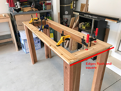
Position the front and rear trim pieces on the stand by aligning the marks on the ends of the boards with the edge of the legs. Make sure that the interior edge of the trim piece is as flush with the edge of the top supports as possible.
If you have a larger framing square, use it to check and make sure that the front and back trim pieces are square. Place the short end of the square on the front top trim piece and point the long end towards the edge of the back top trim piece. If the pieces are square the edge of the back top trim piece will align with the long edge of the framing square. If the trim pieces are not square, then adjust the position of one piece at a time left or right until both edges are flush with the framing square.
If you don’t have a large enough framing square you can basically accomplish the same thing by just test fitting the left and right top trim pieces until all 4 pieces of the top trim line up. Once in position, clamp the trim pieces down for now – don’t glue and nail them yet.
Next, measure the length of the left and right top trim pieces (see part 13 in the plan set). To get the tightest fit between the front and back trim pieces, cut the side trim pieces about 1/8 – 3/16″ long and trim the pieces slightly until they fit just right.
The edges of the side trim pieces will sit flush with the edge of the front and back top trim pieces if they are square. If they don’t, either adjust the left or right position of the front or back trim pieces as described above or double-check the length of the front and back pieces to make sure they are the same. Once the side trim pieces are square, clamp them down as well.
Apply a line of wood glue and attach the top trim to the stand using 1 1/4″ nail brads or finishing nails. Do this one piece at a time, leaving the other pieces clamped down securely in place. Reapply the clamps to all 4 pieces once glued and nailed and let them dry overnight.
Step 9 – Cut Bottom Frame Supports
(PART #2 IN PLAN SET)
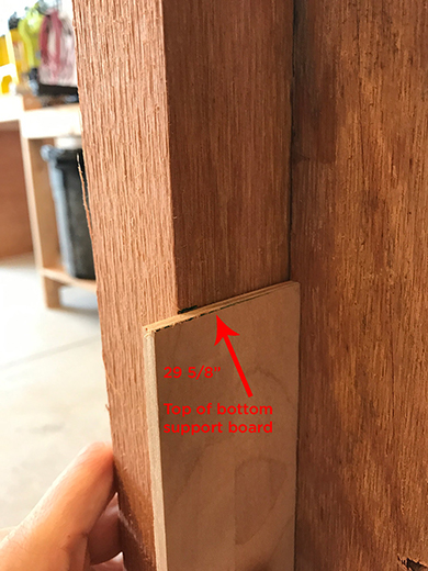
The bottom frame supports sit directly below the top frame supports. Double-check the inside to inside measurement where the bottom frame supports will be installed (about 29 5/8″ – 29 3/4″ off the ground) to make sure that the interior width is exactly the same as top frame supports.
Measure and mark the length of the bottom frame supports and cut 2 pieces to the exact same length. It is important to get the height of the bottom frame supports correct, as the cooler support pieces (see part #15 in the plan set) are attached to the front and back bottom frame supports.
First, make sure the ground is level first then measure up (from the ground)on the inside edge of the front leg and make a mark the measurement.
One easy way to make sure the height is the same is to cut a piece of scrap wood to 29 5/8″ and use it as a template to mark the height mark on the leg. This is the height that the top edge of the bottom frame support will sit at.
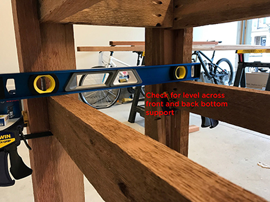
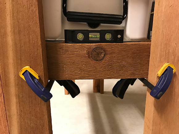
Clamp one side of the bottom frame support to the leg, then move the other end up to the 29 5/8″ mark. Clamp this end in place as well. Use an I-Beam level to make sure that the bottom support is sitting level, and adjust one side as necessary until the level bubble is in between the lines on the middle of the gauge. Repeat this process for the back bottom support.
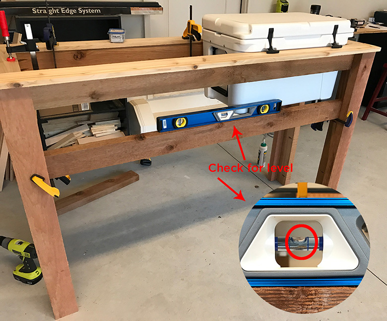
Once both of the front and back bottom supports are in place, use the I-Beam level to make sure that both supports are sitting at the same height and are level. Place one end of the level on the front support and the other end on the back support so it sits across the width of the support pieces. The level bubble should sit in the middle of the guage. Make sure you check for level on both the left and right-hand sides, and the
middle as well. If adjustments are needed, move just one of the bottom support pieces until both sit level.
Place your cooler into the stand (this is why it was necessary to install the top trim piece in step 8), and use a piece of scrap wood to place in between the front and back bottom supports. Make sure that the bottom of the cooler rests on your “test”.(scrap wood) cooler support when the piece is flush with the top of the bottom support boards.
The cooler should be fully seated within the stand upon the top trim pieces, and the bottom supports should be just high enough so that the cooler support pieces will provide a firm base for the cooler to rest on once it is full of ice and drinks. Make new position marks if the actual height of the bottom supports was less or more than the original height mark. For the Yeti Tundra 45 model, the height of the bottom support should be right at 29 5/8″ – 29 3/4″ from the ground.
Drill pocket holes in the short ends of the bottom support pieces as you did in step 5 for the side supports. Add a line of wood glue and re-position the front support into the frame and re-check for level.
Apply the clamps again to keep the support steady, and drive the pocket hole screws. Do the same for the rear bottom support, again checking for level both on the rear bottom support and across to the front bottom support. Drive the pocket hole screws and leave both pieces clamped to dry overnight.
Step 10 – Cut Bottom Side Supports
(PART #3 IN PLAN SET)
The side supports for the bottom of the frame are made exactly like the top side supports in step 7. Use a measuring tape to double-check the width of the top side support before cutting. If you have a laser distance measuring tool use it for this measurement, as the laser measure can be more accurate than a tape measure in narrow or inside-to-inside distances. Offset the pocket holes the same way you did in step 7 as well.
Test fit the side supports and use a smaller torpedo level before driving the pocket hole screws. The longer 6″ Kreg pocket hole driver bit is harder to fit into this space, so you may need to use one of the smaller 3″ Kreg pocket hole driver bits. Make sure you run a line of wood glue before driving the pocket hole screws, then clamp and let the wood glue dry.
Step 11 – Cut Cooler Supports
(Part #15 In Plan Set)
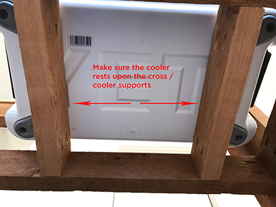
You have already test fit the cooler supports in step 9 to make sure they are positioned at the correct height. All you need to do now is double check the width measurement and attach the cooler supports to the front and back bottom frame pieces.
With the cooler still in the stand, measure the width between the inside of the front bottom support and the inside of the rear bottom support at the position just inside of the rubber cooler feet pads. The width should be equal to the width of the top and bottom frame side supports. Cut the two cooler supports to the same length, then test fit them within the frame. Place each cooler support just to the inside of the rubber cooler feet and make a mark on the
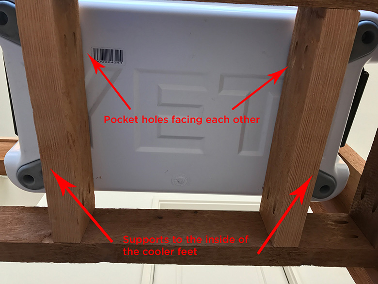
center of the cooler support and on the bottom support so you know where to align the two pieces. Take the cooler out of the frame and set it aside.
Drill the pocket holes on the cooler supports so that the holes on both supports face the inside towards each other. Once the pocket holes are drilled place the supports back into the frame and clamp them in place. Use the speed square to make sure that the cooler supports are square to the front and back bottom supports, then re-tighten the clamps to hold the cooler supports steady. Drive the pocket holes (again, the 3″ pocket hole driver bit may be easier than the 6″ bit in this tighter space).
Step 12 – Cut & Install Front, Back & Side Interior Trim
(PARTS #5 & #6 IN PLAN SET)
The front, back and side interior trim pieces are made out of the 1″ x 4″ board. They are finished using a 45-degree chamfer router bit, which really gives the cooler stand a nice dimensional, finished look.
If you have not used a router before don’t worry – it’s more intimidating than it looks. Once you learn how to set the router bit correctly actually routing the wood is fairly easy after a couple of practice runs.
If this is your first project using a router take some scrap board and practice routing the board edges before you route the actual trim pieces. I have a Bosch Colt palm router that is very easy to set up and use and fits perfectly within one hand. The palm router size makes it much easier to hold the board with one hand and operate the route with the other (as compared to a larger router that typically requires both hands to operate).
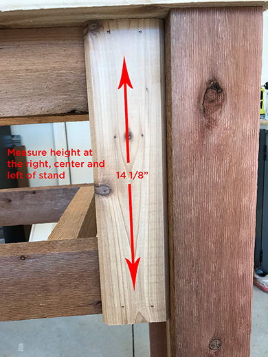
Measure the length of the trim pieces first by taking a measurement at the left, center and right positions on the front of the cooler stand. You measurement should be from the bottom of the top trim piece to the bottom edge of the bottom frame support.
It’s quite possible that the length measurements will vary a little bit (about 1/8″ or so), which means you will want to cut all of the trim pieces to the longest length so they align properly once installed. If there are small differences in length you can trim an individual piece to the correct measurement as you install them (since you cut all of the pieces to the longest length).
You will have a little leeway due to the fact that the exterior trim pieces (see parts 7 & 8 in the plan set) will sit on top of the interior trim and hide any small differences in the length of the interior trim pieces.
The length of the trim should be about 14 1/8″. Cut the first piece and test fit it against the front of the stand. You will need 17 trim pieces for the front, 17 for the back, and 3 for each side of the stand. Cut all of the trim pieces at the same time, again using the first piece as your guide.
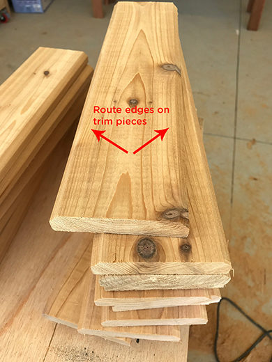
Use the 45-degree chamfer router bit to create the beveled edge from one end of the trim piece to the other (lengthwise). Route both the left and right edges of the 36 trim pieces, and just one edge of 4 of the trim pieces. You will see why only one edge needs to be routed on 4 of the pieces in just a second.
Once you have routed all of the pieces, install each piece by attaching it to the top and bottom frame supports on the front and back of the stand. Apply wood glue to the top and bottom portions of the trim where it meets the top and bottom frame supports and nail them in place with 1 1/4″ nail brads or finish nails. Make sure that you fit each trim piece snugly against the adjoining piece as you install them. Make sure there are no (or minimal gaps) between the trim pieces. Install the remaining 16 trim pieces on the front and back, and 2 on the sides.
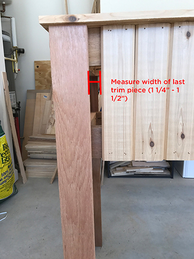
The 17th piece that you install on the front and back, and the 3rd piece on the sides will need to be trimmed down to a smaller width, as shown below.
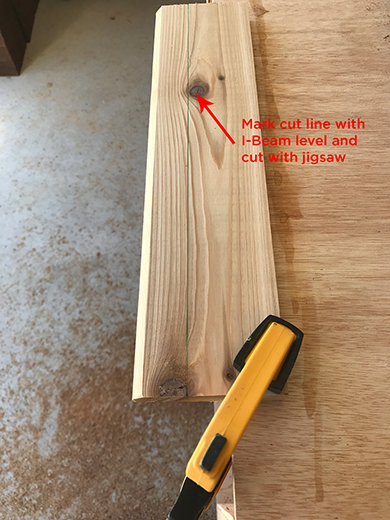
To cut the final trim pieces, first measure the distance from the left edge of the 16th trim piece to the edge of the stand leg. This width should be about 1 1/4″ – 1 1/2″. Use your tape measure or a regular ruler to mark the width on both ends of the this trim piece.
Make the mark on the side of the trim piece that will face the inside – it’s easier to cut the piece with the mark on this side. Take your I-Beam level and align it with the width marks, then adjust the level until the bubble is in the center of the gauge. This indicates that the line is straight, so mark the line with your pencil or pen.
Clamp the trim piece to a sturdy surface so that a portion of the trim that you will cut hangs off the table. Make the cut with a jigsaw along the line you just marked. It’s fine to make this cut a little bit narrower than the actual width measurement. This will give you a little wiggle room when you install the piece and it also helps avoid having to make multiple cuts to make it fit the exact width. The exterior trim pieces will hide any small gaps between the last trim piece and the stand legs.
Fit the last trim piece in place, glue and nail. You may need to use a small straight edge or pry bar to snug the last trim piece in place as shown in the photo below to the right.
Step 13 – Cut And Install The Front, Back & Side Exterior Trim
(PARTS #7, #8, #9 & #10 IN PLAN SET)
The exterior trim pieces are made out of the 1″ x 2″ board. They just form a simple rectangular frame that is mounted to the outside edge of the interior trim pieces. Verify that the measurements in the plan set match the actual dimensions on the stand. Cut each piece a bit long and trim it to fit as needed to make sure the fit is nice and tight.
Install the top exterior trim piece first on the front of the stand. Make sure that it sits flush against the bottom of the top trim piece.
Install the bottom exterior trim piece next, making sure it is flush with the bottom of the interior trim pieces you just installed in step 12. Install the left and right exterior trim pieces last, cutting each piece incrementally to just the right height. Repeat on the back and sides.
Run a line of wood glue on the back side of each exterior trim piece and attach to the interior trim pieces with 1 1/4″ nail brads or finish nails.
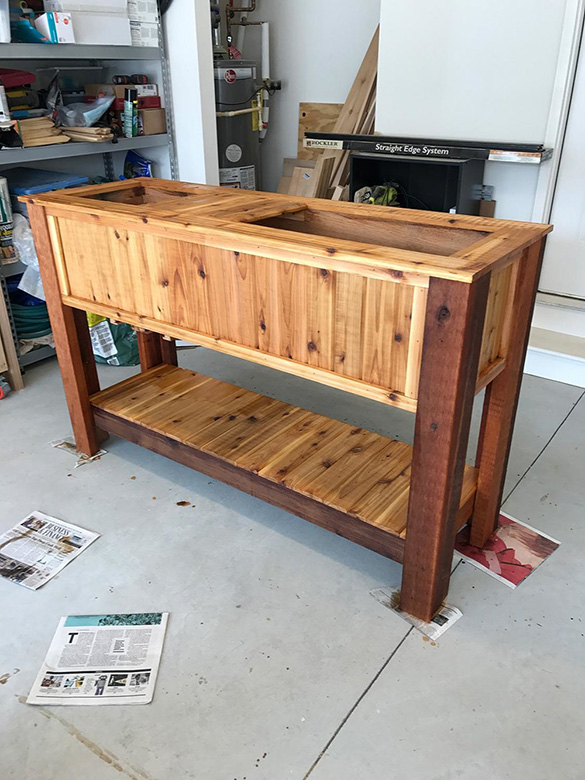
Step 14 – Cut Trim & Supports For Top Serving Area
(PARTS #14 & #16 IN PLAN SET)
The “top serving area” (for lack of a better description) is a space for items such as napkins, cups, drink mixers, etc.
Home Depot sells plastic planter boxes (for plants) that are the perfect size to fit in the top of the cooler stand. The boxes make good ice buckets for wine bottles or any other drinks you would like to keep cold but not in the cooler. They are the exact length/dimension of the space on the stand (15″ x 8″), and have a small lip at the top of the box that rests perfectly on the top trim pieces. They are $5 each as well! Purchase two of them in the black/bronze color.
The trim pieces for the top serving area are cut and routed exactly the same way as the front and side trim pieces in step 12.
Start by placing the two planter boxes in the left-hand side of the stand and push them together so that the lip on the top of the boxes are touching. Put the cooler back in the stand on the right-hand side as well.
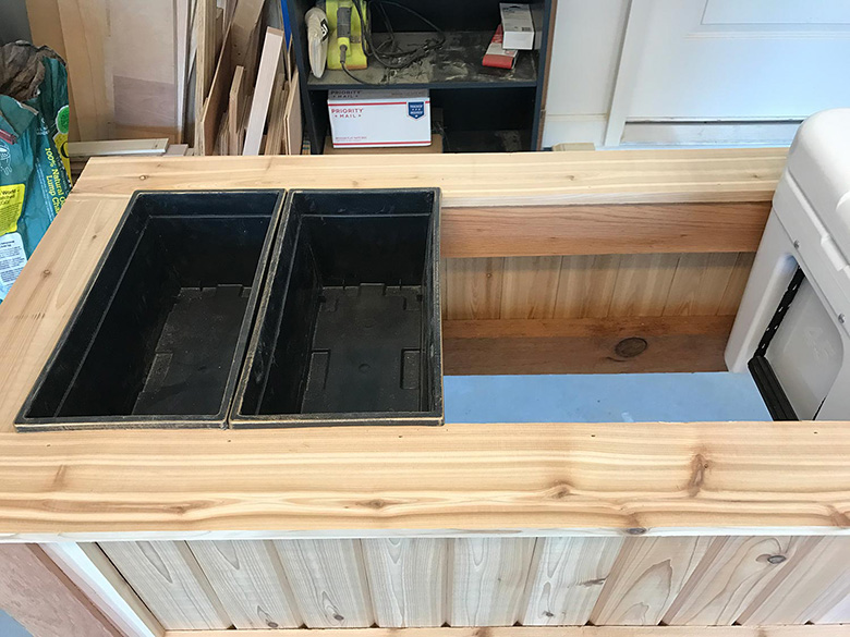
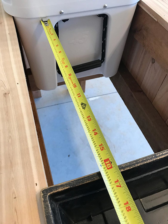
Measure the distance from slightly inside the right-hand planter box (the one closest to the cooler) to just before the edge of the cooler. This is the width for the serving are trim supports, and it should measure 16.5″.
Cut two of these supports to the exact same length using a piece of the remaining 1″ x 2″ exterior trim that you just installed on the front, back, and sides of the stand.
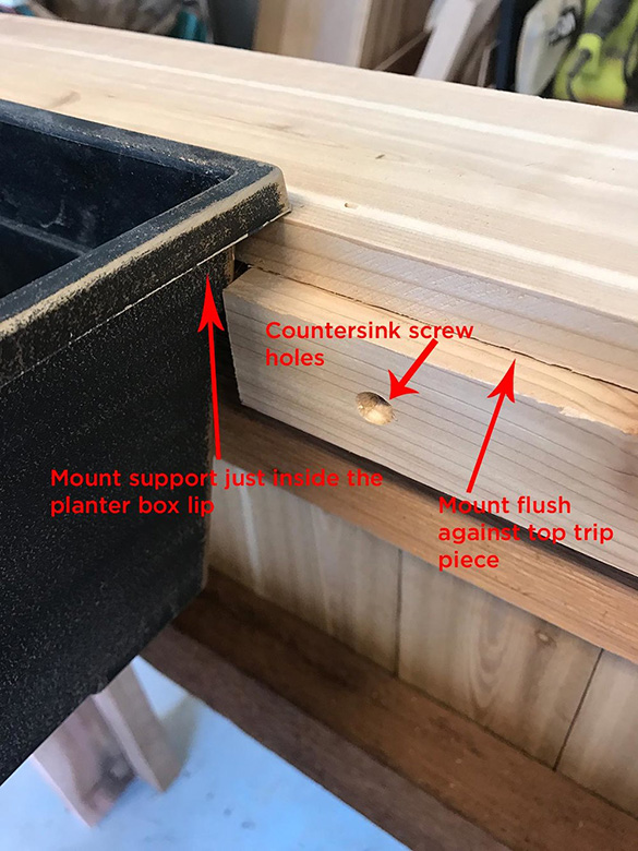
Test fit the supports in the top serving area and trim incrementally as needed. I used a countersink drill bit to drill 3 holes on the top trim support so that the screws that attach it to the stand frame sit recessed in the wood. You can’t really see these screws, but it still provides a nice touch. Once you have the top trim supports cut to the correct length, mount them in place so that they sit just under the front and back top trim pieces.
If you have a level that will fit in the space use it to make sure that the supports are level as you install them. Make sure that they are level across (front to back) also. Use #8 1 1/4″ exterior screws (preferably in black or gray) to attach the supports to the stand frame. If one side of the 1″ x 2″ board is rough, mount that side facing down towards the floor and position the smooth side of the board up. The trim pieces will rest against the smooth edge of the support.
Next, measure the inside-to-inside length from the back piece of the top trim support to the front piece. This is the length of the trim piece, and it should measure 14 3/8″. Cut a total of 5 trim pieces to the same length.
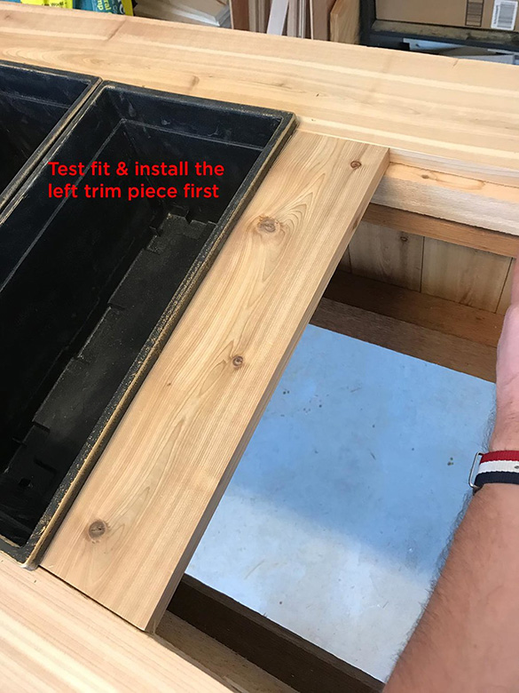
The 5th trim piece will be installed next to the cooler. You will need to trim the width of the 5th piece just as you did with the front, back and side interior trim pieces in step 12. Test fit the 4 trim pieces in the stand and make sure they are sit flush and flat on the supports.
The top of the top serving area trim should sit flush with the front and back top trim pieces. Trim any length as necessary on each board. Once all boards are trimmed to the correct length, route 45-degree edges on both sides 4 of the trim pieces, and on the left-hand side of the 5th piece.
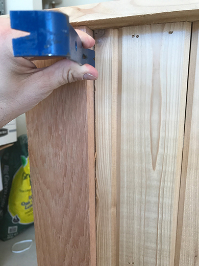
Install the far left trim piece first (the one closest to the planter box). Add a line of wood glue to both ends where the trim piece will rest on the support. Use the speed square to make sure that the trim piece is square to the front and back top trim pieces, then drive 1 1/4″ nail brads or finish nails at an angle so that they pass through the trim piece and into the trim support piece. If the trim pieces are not square the remaining pieces won’t fit correctly. Repeat until you get to the 5th trim piece next to the cooler.
For the 5th trim piece, measure the distance from the edge of the cooler (in the center of cooler width) to the right edge of the 4th trim piece. It should be about 2 5/8″ – 2 11/16″. Mark this distance on the
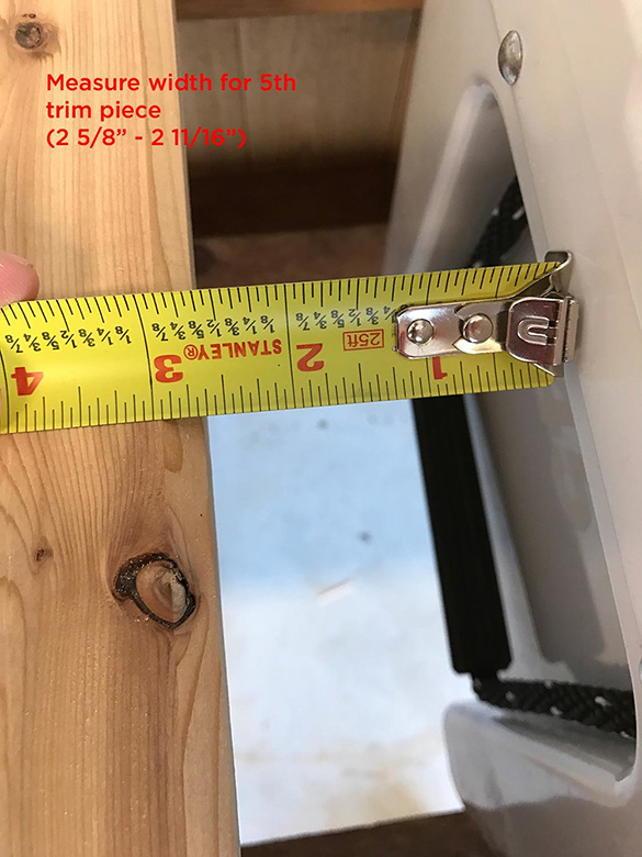
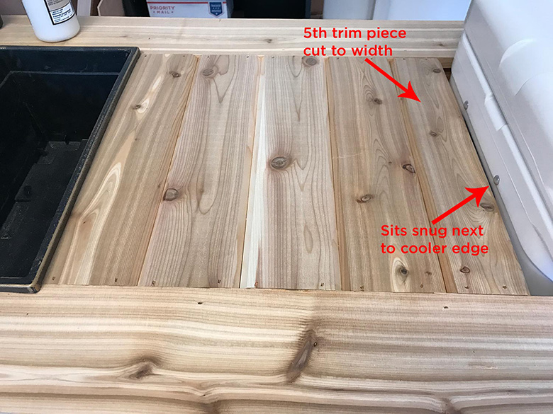
5th trim piece, scribe a straight line with your I-Beam level and cut to width with a jigsaw. Again, cut it slightly less than the actual measurement so there is a little leeway between the right edge of the trim piece and the cooler. Test fit the 5th trim piece and trim as needed. Once the width is correct route the left edge of the piece and install it in the stand with wood glue and nail brads or finish nails.
Step 15 – Cut Bottom Shelf Supports
(PART #4 IN PLAN SET)
You’re almost done! Just a few more pieces to cut. The bottom shelf is handy for storing many different items, such as buckets, plates, or anything else you want to keep close by.
The bottom shelf supports are cut just like the top and bottom frame supports in steps 4 & 9. Measure the distance from the inside of the right hand leg to the inside of the left hand leg. It should match the length of the top and bottom frame supports. Cut two pieces out of the 2″ x 4″ board at the same length. Test fit the front bottom shelf support and trim to length, then repeat for the back bottom shelf support. Drill 2 pocket holes on each side, offset as you did in step 7.
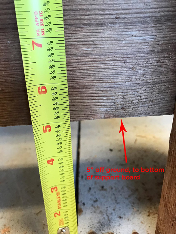
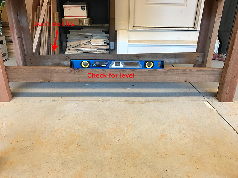
To install the bottom supports, first check that the floor is level. If it isn’t the bottom supports won’t be level and in turn, the bottom shelf will not sit level.
Measure 5″ off the ground and make a mark on the stand legs on the left and right sides. Place the front bottom shelf support in the frame and adjust it to the point where the bottom of the support board is level with the marks you just made on the legs and clamp it in place.
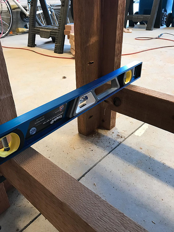
Use the I-Beam level to check and make sure the shelf support sits level and adjust as needed. Do the same for the back bottom shelf support and clamp in place. Place the ends of the I-Beam level on the front and back bottom shelf supports and check for level across the 2 boards.
Once both pieces are level and correctly positioned, update your alignment marks if needed. Remove the clamps from the front bottom shelf support, apply a line of wood glue to each end and re-position them while making sure the edge of the support board is aligned with your marks. Drive the pocket hole screws and re-apply the clamps and let it dry overnight. Repeat the process for the back top support.
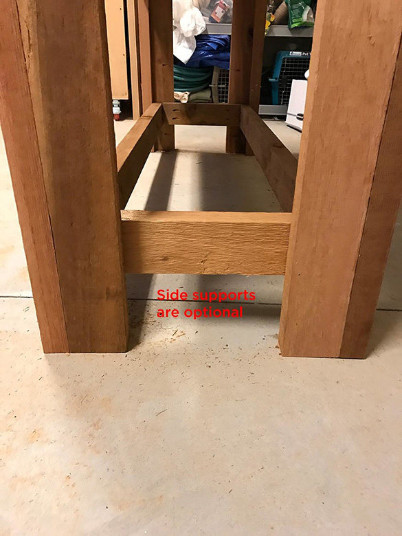
You can also add side supports to the bottom shelf if you would like, but they are not really necessary. If you do choose to add them, cut and install them just like the side frame supports in step 7.
Step 16 – Cut Bottom Shelf Trim
(PART #11 IN PLAN SET)
The trim for the bottom shelf also is cut exactly like the front, back, side and top serving area trim pieces. Check the measurement from the outside edge of the back bottom shelf support to the outside edge of the front bottom shelf support. Check this width on the left, center and right sides of the bottom shelf support to make sure it is the same. It may vary slightly (1/8″ or so) as you move across the bottom shelf. If it does, just cut all of the bottom shelf trim pieces to the same (longest) length.
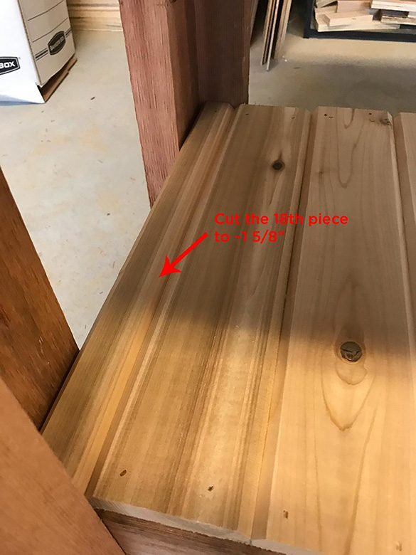
Cut 18 pieces total to the required length. You will have to trim the 18th piece to fit just as you did with the interior trim pieces in step 12. Route a 45-degree edge on 17 of the pieces, and on the right-hand side of the 18th piece.
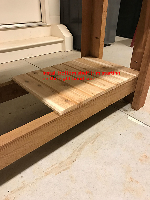
Install the trim pieces starting on the right-hand side. Add a line of wood glue on both ends of the trim piece where it will rest on the bottom shelf supports. Nail the pieces in place with 1 1/4″ nail brads or finish nails. As you work across the bottom shelf make sure the trim pieces fit together tightly and are square before nailing them down. The width of the 18th trim piece should be about 1 5/8″. Trim it to size, test fit, route the right edge and glue and nail in place.
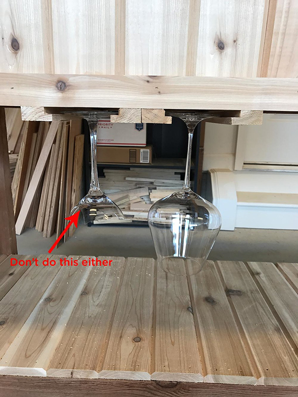
Step 17 – Wine Glass Rack
(PART #17 IN PLAN SET)
The wine glass racks are another nice touch. They provide a convenient place to store glasses outside (and hopefully prevent them from being broken when not used). The rack is very simple to make. It consists of 4 pieces of the 1″ x 2″ board, with a 1/4″ rabbet (groove) cut on the side of each piece. The base of the wine glasses slide into the rabbet.
Measure the width from the outside edge of the front bottom frame support (right under the bottom of the front interior trim) to the outside edge of the back bottom frame support. Cut 4 pieces out of the 1″ x 2″ board used for the exterior trim. Test fit each piece and trim the length slightly to make sure the rack is flush with the exterior trim pieces above it.
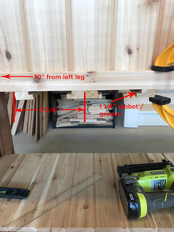
Use a 1 1/4″ rabbet router bit to route the groove on the top inside edge of each piece. To determine the width between the two pieces get one of your favorite wine glasses and have a partner hold the rack piece up on the left side as if it were mounted to the bottom of the stand.
Place the wine glass in the rack, then position the second rack piece on the right so that the glass hangs by the base of the glass. Leave a little room for the glass to move around in the rack, you don’t want it so tight that the glass is difficult to slide in and out of the rack.
Make marks on the outside edges of the rack for alignment. You can also shoot nail brads in the rack as you position it, then come back and screw it to the bottom frame support with exterior screws. Make small dots on each end of the board where the screws should go. Use a countersink bit to drill the screw holes in each piece of the rack. Attach the rack to the bottom frame supports with 1 1/4″ exterior screws. BE CAREFUL AND GO SLOW as you drill the screws. If you drill too fast the board may split.
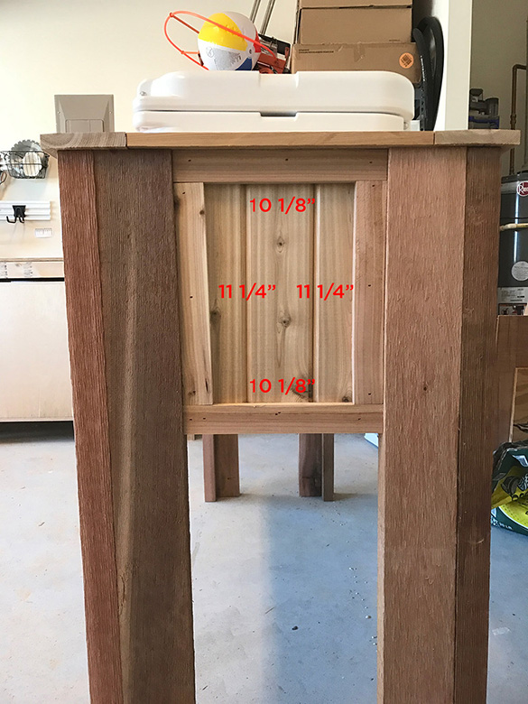
Based on the wine glasses that I used, the left side rack piece in the photo below measured 10″ from the outside of the left side stand leg and 5 3/4″ from the outside edge of the left rack piece to the outside edge of the right rack piece. Once you have the measurements for the left side rack, install the third rack piece flush against the second. Space the fourth rack piece out at the same distance as the first two pieces and attach it to the bottom frame support.
Step 18 – Stain
A high-quality stain will help the stand last against the outdoor elements and weather. I used PPG/ Sikkens ProLux Cetol Log & Siding Stain in the Cedar 077 color. It’s fairly expensive, but this stain is often used on log homes or other wood exterior siding so it will help the stand last as long as any other comparable stain.
The stain seals the wood very well to protect it against the outdoor elements. You can use another stain that is a bit more budget-friendly such as Minwax Helmsman Indoor/Outdoor Spar Urethane as an alternative.
I do recommend spending the money on a high-quality stain/urethane to help the stand last as long as possible outdoors.
It takes about a 1/2 gallon to apply two coats to the entire stand. Make sure that you stain the underside surfaces as well (turn it over and stain the bottom of the frame supports, bottom trim and the interior pieces) to seal all of the pieces. 2 coats are recommended to get the optimal protection that the stain provides.

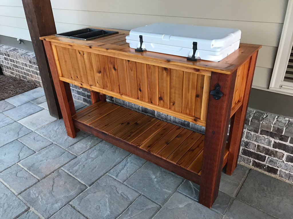
Step 19 – COMPLETE!
1 Comment
HouseChores
August 31, 2025 at 2:38 amGreat review! I’ve been considering the Yeti Tundra 45 for my patio, and your insights on its durability and design really help. I love the idea of it being both functional and stylish. Thanks for sharing!