
Thanks for stopping by Southeast4x4trails.com! If you are looking for a detailed guide on how to install a GMRS radio or Ham radio in your Jeep or off-road vehicle you have come to the right place. Keep reading for more details about this 5-part series on my radio install project.
If you have found your way here via Google, this site is about the Jeep, 4×4, and off-road community in the Southeast US. Check out the home page for an interactive Google map of trails, off-road parks, forest service roads, points of interest and more in the GA, TN, NC, and SC areas. The Journal has other articles similar to this one on topics of interest such as “how-to” guides, trails and places to visit, and local history. The Resources page has many links to mapping, GIS, USFS forest areas, and technical info.
This is the third in a series of 5 posts that detail the install of a Midland MXT400 MicroMobile GRMS radio and Icom IC-2730A ham radio in my Jeep Wrangler TJ. You can adapt this information to any vehicle, it doesn’t have to be a Jeep TJ or even a Jeep!
This post will cover the installation of the radio antenna mounting brackets, attaching the antennas for both radios to the mounting brackets, and the initial routing of the antenna coaxial cables.
Part 1 includes a complete list of all the radio gear, tools, parts, and hardware that I used and Part 2 includes a radio system guide and wiring diagram.
If you want to jump directly to the install info just click one of the links below:
- Part 1 – Project Details, Gear, Parts and Tools
- Part 2 – Mounting the Midland MXT400 GMRS Radio and Icom IC-2730A Ham Radio
- Part 3 – Mounting the Radio Antennas
- Part 4 – Power, Wiring and Fuse Block Installation
- Part 5 – Radio Power Wiring and Antenna Coaxial Cable Installation
Before we get started I’d like to ask you for a favor. If you find this post useful please consider supporting this site by purchasing any of the items listed in the post through the links provided. The links to Amazon are affiliate links, and the small commission that I may earn keeps this site running so I can continue to provide helpful information.
Parts List
The following parts were used in this post:
■ Larsen NMOKHFUD NMO 3/4” Mobile Antenna Mounts + Coaxial Cable w/ No Connector (Qty: 2)
■ Larsen NMO 2/70B Antenna (For Icom IC-2730A)
■ Larsen NMO450CHW Antenna (For Midland MXT400)
■ Laird SBT3400 NMO Straight Antenna Mounting Brackets (Qty: 4)
■ NOTE: This straight-style bracket will NOT work with a Jeep JK or JL. You will need a JK or JL-specific bracket with a 3/4″ NMO hole such as this one from Antenna Farm or Topsy Products.
RadioReference.com Forum
Please note that some of the information in this post is adapted from a forum thread that I posted on RadioReference.com named “Multiple Antenna Question for 2M/70CM” I was fortunate enough to have several very, very knowledgeable and helpful people respond to my post and help me figure out the installation plan for this project. I have including some of the details from that forum thread in this post for your benefit. Some of the knowledge behind the various components of the radio system are key to understanding why those components were selected and what makes their performance superior to your average radio gear install.
Antenna Ground Plane – Why Is It Important?
Don’t skip over this section – it is important and relates to how well your radio will perform.
When it comes to installing antennas for mobile radios on vehicles, the generally accepted “ideal” scenario is one where you are able to mount the antenna on top of a metal roof on the vehicle. The antenna is mounted on the roof by either drilling a hole through the roof and installing the antenna mount (such as an NMO) or by using a magnetic mounting base.
Either of those mounting methods allows the metal surface of the roof to connect to the antenna, where the metal roof of the vehicle services as what is called a “ground plane”. A ground plane is a “flat or nearly flat horizontal reflecting surface that serves as part of the antenna and reflects the radio waves from the other antenna elements.” (Wikipedia)
So, if you are mounting the antennas on a Jeep you do not have a metal roof – it’s either a fabric material if you run a soft-top or fiberglass if you run a hardtop.
Yes, there are other flat metal surfaces to mount the antenna on, but the size and area of the flat metal surface is important if that surface is going to act as a ground plane for the radio antenna(s). If you are using a GMRS radio, 2-meter or 70cm Ham radio, there isn’t a flat metal surface large enough on the Jeep to serve as a ground plane.
What is important is that you use what is called a “no ground plane” antenna for the frequency that your radio will transmit on. Both of the antennas that I installed are “no ground plane” antennas – the Larsen NMO450CHW for the Midland MXT400 GMRS radio and the Larsen NMO2/70B for the 2-meter/70cm Icom IC-2730A Ham radio.
In technical terms, both the NMO2/70B and NMO450CHW are 1/2 wave antennas which means that the length of the antenna whip (long metal piece) is equal to 1/2 the length of the full RF wave for the bands they are designed to operate on. This length allows the antennas to work without a ground plane.
The information available on “no ground plane” and “ground plane” antenna setups is virtually endless. If you would like to learn more about these concepts, Google either of those terms but beware it gets very technical very quickly. My goal in this post is to highlight why a “no ground plane” antenna is the correct choice for these radios when they are mounted on a Jeep.
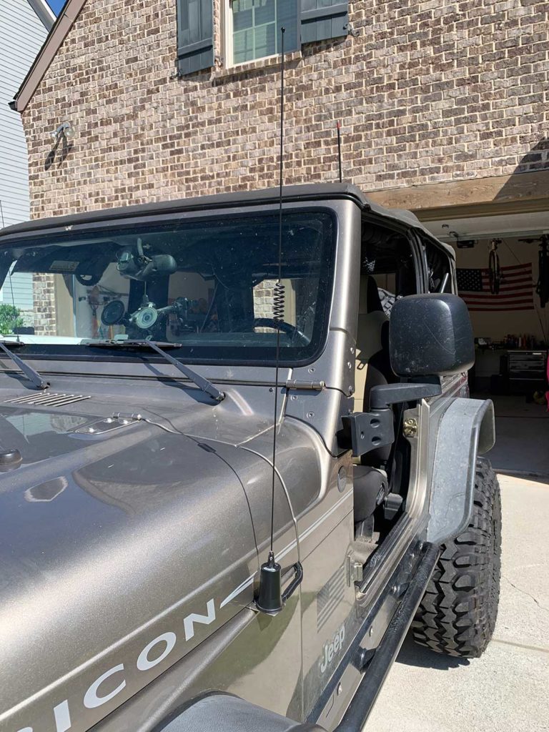
Antenna Mounting Location on the Jeep
I mounted the antennas for the MXT400 and IC-2730A on the front fenders of my Jeep. If you are wondering why I mounted them on the front fenders and not in the rear of the Jeep as many people do, the short answer is mounting any radio antenna on the rear of a Jeep Wrangler is not a good choice if you want to maximize the signal range, quality of your radio communications and the radio’s overall performance.
In part 1 of this series I went into more detail about why mounting the radio antennas on the front fender was a better location, but this is the main takeaway:
Why? Because typically there are multiple obstructions in the rear of Jeep (tire carrier, hard/soft top, other radio antennas, etc.) that affect the path and emissions of the RF waves that your radio antenna transmits. It alters the radio wave propagation pattern which means it impacts (makes it worse) the radio’s performance.
If you would like to read more about this topic, visit the ‘Project Background and Detail’ section in Part 1. In fact, when I first installed the MXT400 I mounted the antenna on the rear tire carrier before I had any clue about the disadvantage mounting it in that location.
1. Reinforce the Antenna Mounting Brackets
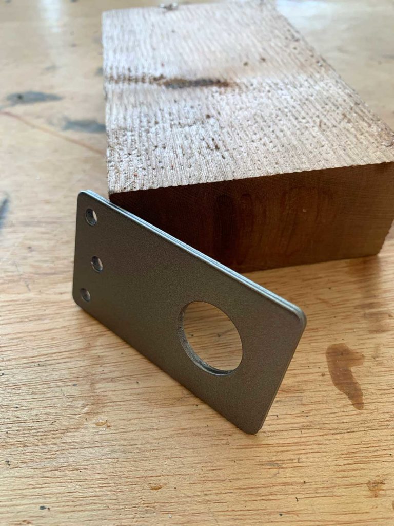
Both of the antennas are mounted on Laird SBT3400 NMO straight brackets. You will need 4 total brackets, 2 for each fender. Joining two brackets together provides a stronger base that is less likely to bend the brackets.
Another lesson learned from the first time I installed the antennas – if the antenna coil gets hung up in trees or branches, it will bend the mounting bracket.
After I initially finished this project, I went on a trip the following weekend to an area that had pretty thick tree cover throughout the entire trail. The leaves on tree branches kept getting caught in the open coil on the Ham radio antenna (Larsen NMO2/70B) and it almost ripped the mounting bracket off the fender. Also, another handy trick is to put a piece of heat shrink around the antenna coil so leaves and branches will not get caught in it to start with (see the end of this post for a photo).
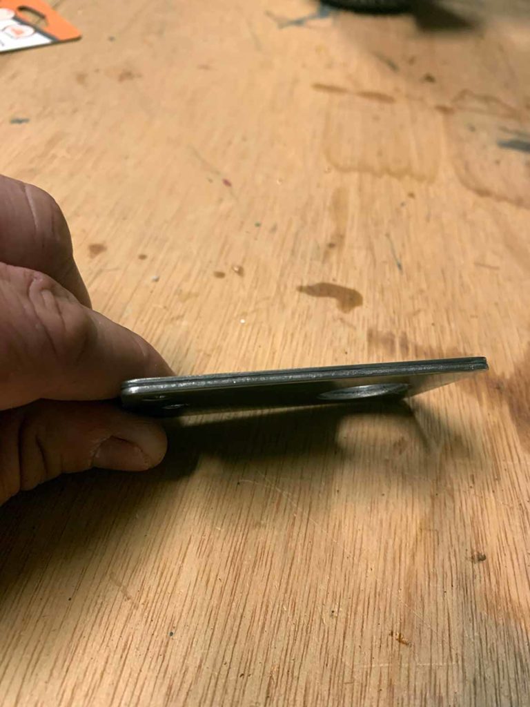
First, use a strong adhesive such as Gorilla Glue Clear Epoxy (part 4200101) to bond two of the mounting brackets together. Follow the directions on the package to mix the epoxy together. You can use the package as a mixing tray as well.
Coat the inside of both brackets with the epoxy and align them by sliding them into position with your fingers. They will slide pretty easily, so make sure all 4 sides on both brackets are aligned and square. While holding both brackets together with one hand, attach a clamp and slowly tighten it to make sure that the brackets do not slide out of alignment.
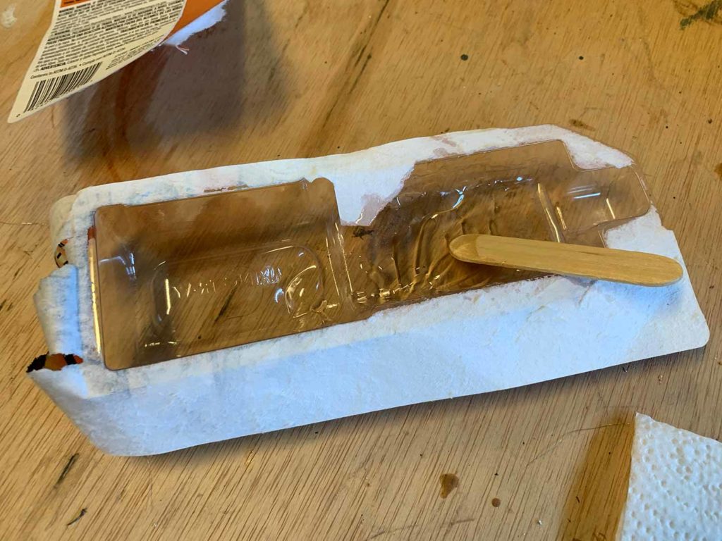
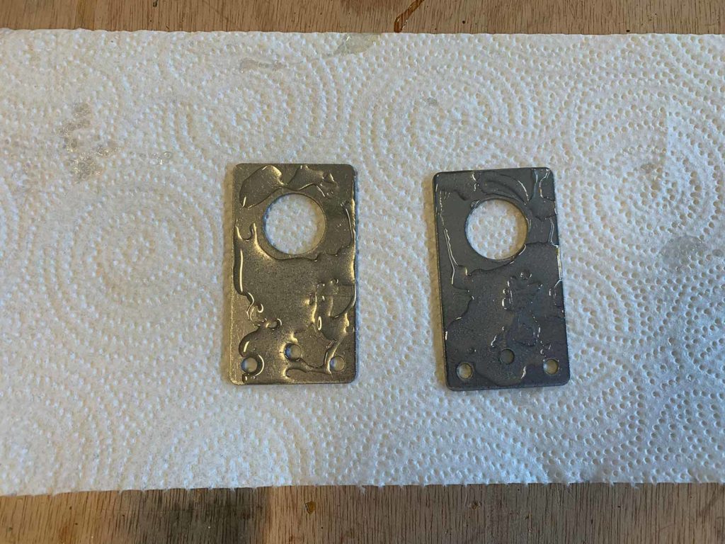
Once the brackets are clamped together use a cloth to wipe off the excess epoxy around the edges. The less epoxy on the top, bottom, and sides of the bracket the better. Let the brackets sit clamped together for 30-45 minutes to give them enough time to bond and cure.
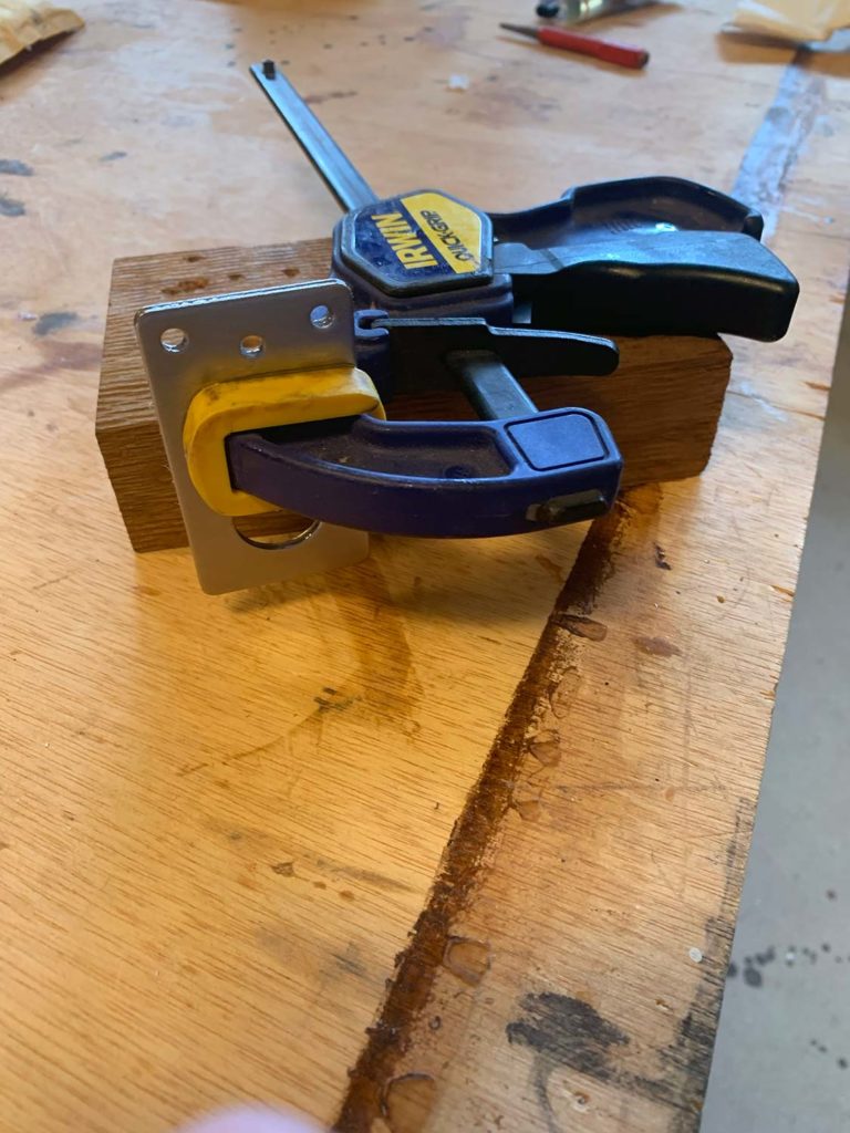
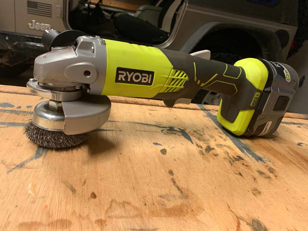
You will wind up with some excess epoxy on the top, bottom, and sides even if you are extra careful. An easy way to clean the brackets up before you paint them is to use an angle grinder such as the Ryobi P421 with a wire cup brush attachment. Use the clamp to attach the bracket to a solid surface, then just run the wire cup brush over the bracket surface until all of the excess epoxy is removed.
You can also use a Dremel tool with a carbon or stainless steel brush attachment to remove the excess epoxy from the sides of the bracket.
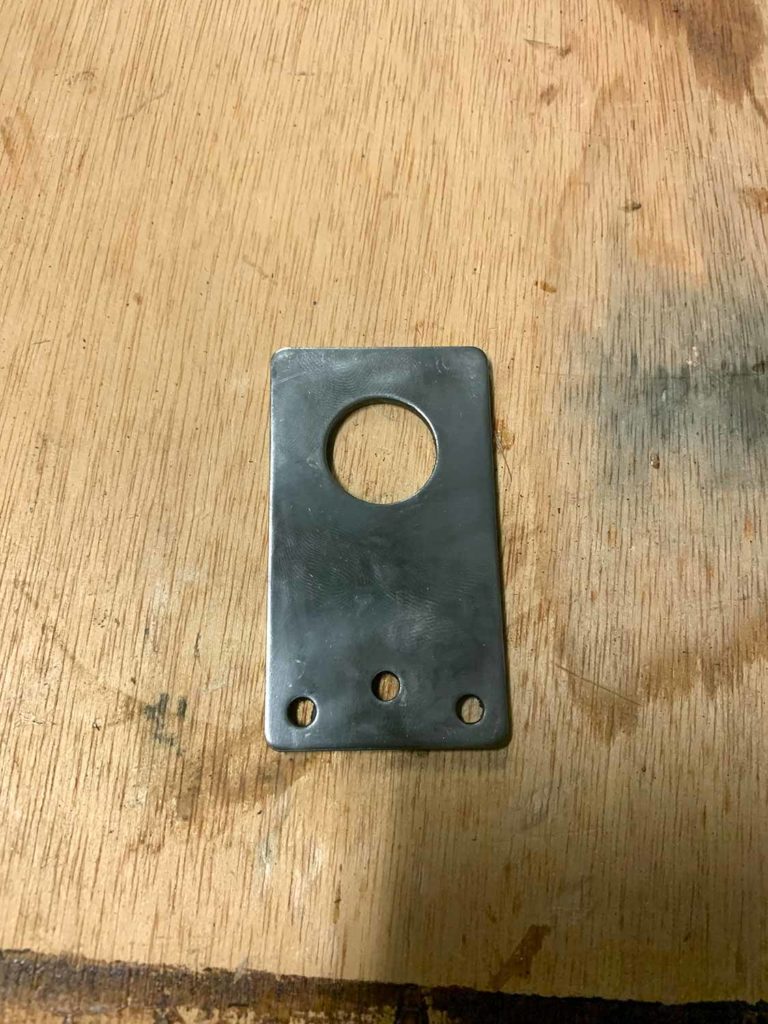
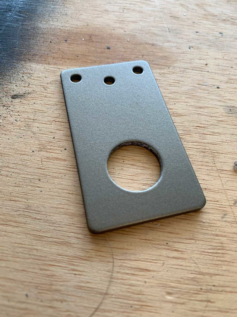
After all of the excess epoxy is removed use a center punch or something pointed to clean out any epoxy from the 3 screw holes on each bracket.
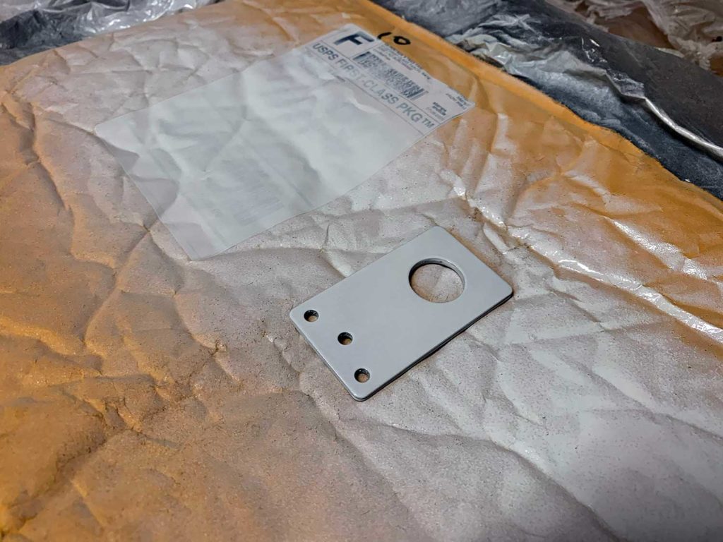
2. Prep and Paint the Mounting Brackets
Prepping and painting the mounting brackets is very similar to painting the radio mounting brackets as covered in part 2 of this series.
Since the brackets are mounted on the front fenders I wanted them to blend in with the rest of the Jeep’s body as much as possible, so I used a can of Mopar Body-Color Touch Up Spray Paint to get an exact paint match. If you are unsure of the color code for your Jeep check the sticker on the door jam on the driver’s side. It usually will include the factory paint color code or you can use this handy reference chart from Quadratech.
Before you paint the brackets, coat them with primer first. I used Rust-Oleum Clean Metal Flat White Primer (7780830).
NOTE: Only prime and paint the top and sides of the bracket. Leave the bottom side of the brackets unfinished so it can make a good ground to the Jeep fender.
The instructions on the can for the flat white primer and flat black protective enamel state to “hold can upright 10-16 inches from the surface and spray in a steady back-and-forth motion, slightly overlapping each stroke. Keep the can the same distance from the surface. Keep the can in motion while spraying. Apply 2 or more lights coats a few minutes apart.”
Follow these directions and apply 3 coats of primer.
Give the primer at least an hour to dry, and take the outside temperature into account as well. I painted the brackets in mid-July in Georgia and the temperature was well over 90 degrees. Don’t rush it, if the primer is still tacky when you touch it give it more time to dry.
Next, follow the directions on the Mopar touch up paint can and apply 3 coats to the top and sides of the bracket. The same thing as the primer applies to dry time. I let the paint try on the brackets overnight after all 3 coats of the Mopar paint were applied.
The last step is to coat the brackets with a clear top coat. I used Rust-Oleum Universal Dead Flat Clear Durable Topcoat (342482).
The instructions on the can for the dead flat clear coat state to “Hold can upright 8-12 inches from surface and spray in a steady back-and-forth motion slightly overlapping each stroke. Keep the can the same distance from the surface. Keep the can in motion while spraying. Apply 3 or more light coats continuously, spraying off the surface with each coat. For best results, apply multiple light coats versus one heavy coat.”
I applied 3 coats and let it dry four a couple of hours before installing the brackets onto the front fenders.
3. Mount the Brackets on the Front Fenders
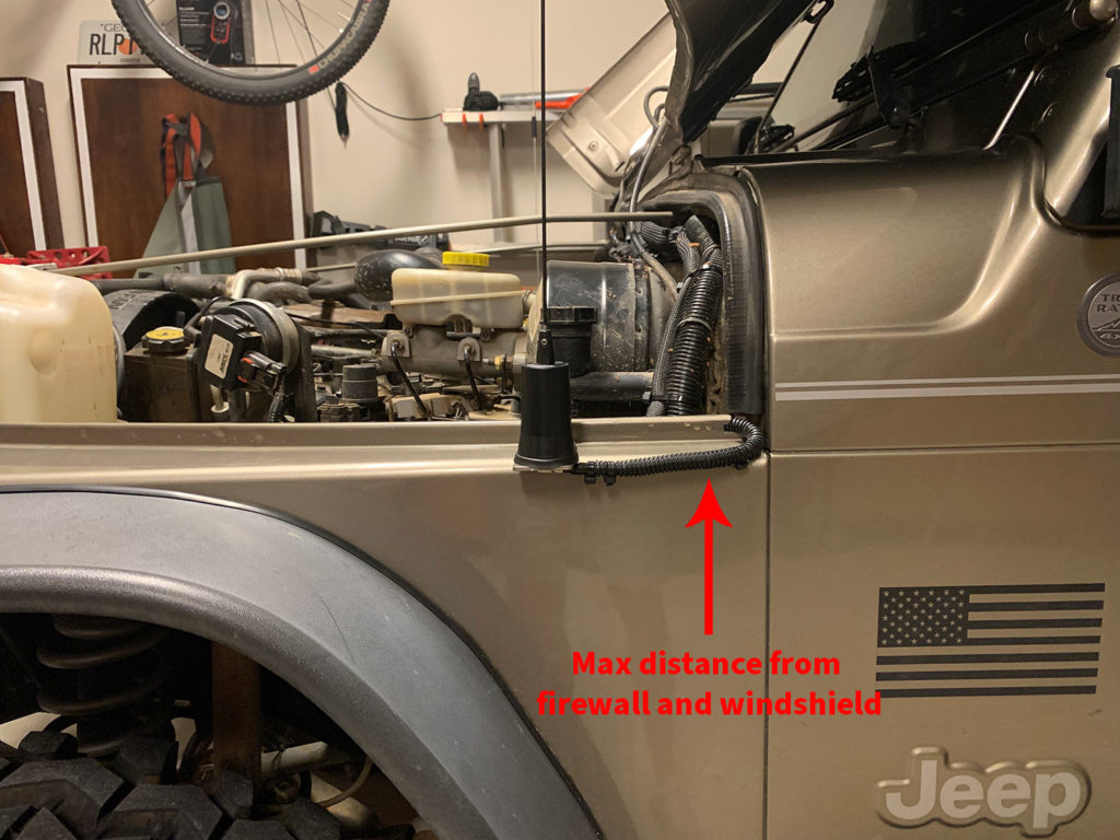
Time to drill some holes in the Jeep (or whatever your rig might be). In general, the goal is to mount the antennas as far forward on the front fenders as possible.
The further the distance from the windshield and the rest of the body, the less the radio signal propagation from the antenna(s) is disrupted (theoretically). There is a physical limit to how far forward you can mount the brackets on the fenders while providing ample support and contact to the body. See the photos below for an illustration of where to mount the brackets.
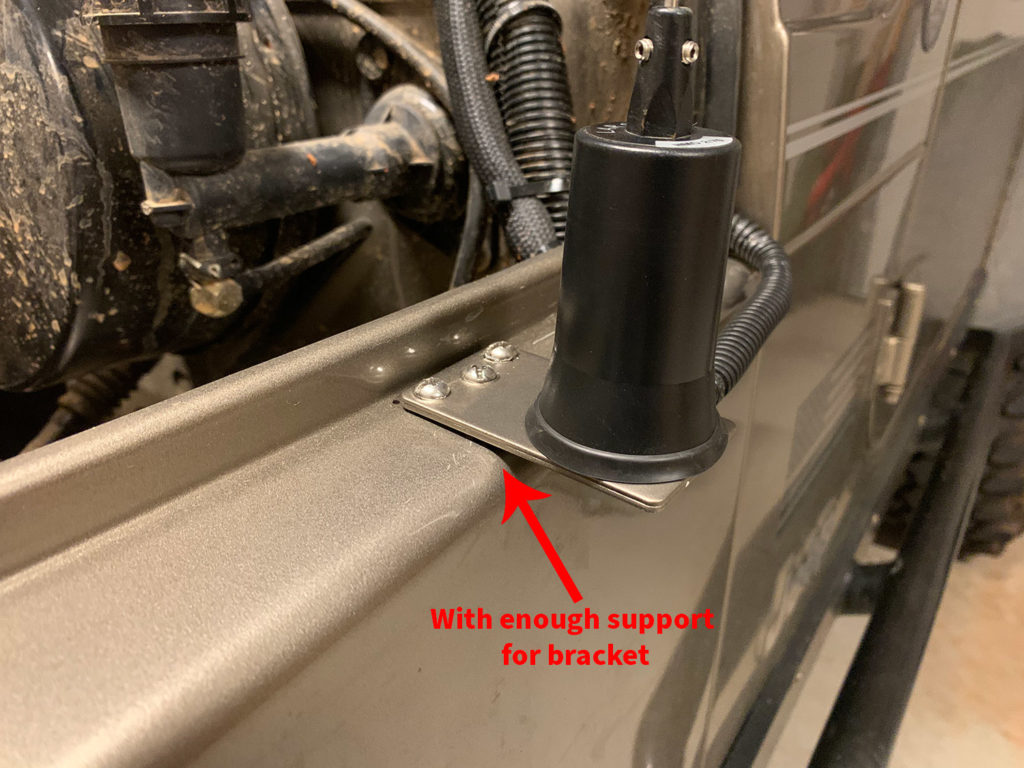
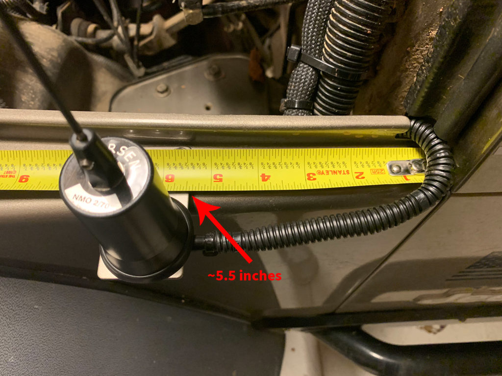
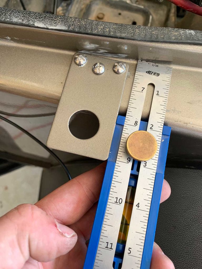
As shown below, the right edge of the mounting bracket is right at ~5.5″ from the body at the firewall. You can test fit the bracket location by placing it on the fender, then sliding it towards the grille (front) of the Jeep to find the point where the bracket is still supported by the fender but is as far forward as possible as shown in the photo above on the right.
Once you have found the best mounting position for the bracket, mark the center of the 3 screw holes with a marker or something that will be easy to see.
To keep the mounting bracket in the position you marked, it is important to start the drill bit where the center of the hole should be (where you marked) to keep everything aligned. If the drill bit wanders off of the center of the hole, the bracket is either going to sit crooked or not fully contact the fender as you want it to.
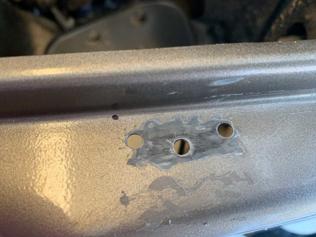
Use a metal center punch to start the hole and help keep the drill bit in the correct place. Use the punch to make an impression on the fender where each of the mounting screw holes should be. This will help keep the drill bit at the center of the hole and from sliding around on the fender. When you start drilling the hole, rotate the drill bit slowly at first and then speed it up as the bit removes the metal..
Use a 3/16″ metal drill bit such as the Milwaukee Shockwave Titanium metal bit to drill the 3 holes for the mounting screws.
Before you attach the bracket to the fender, remove a portion of the paint on the fender so the mounting bracket has a metal-on-metal connection which will create a good ground between the bracket and the body.
I used a Dremel tool with a carbon steel brush attachment to remove the paint. Carefully remove enough paint to match a width that is a little less than the width of the mounting bracket. You don’t want any bare metal on the fender to be exposed outside of where the bracket is mounted.
4. Mount the Bracket on the Driver Side Fender
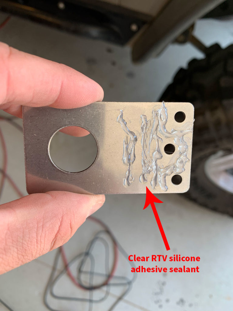
Before you mount the bracket on the fender, run a bead of clear RTV silicone adhesive sealant around the portion of the bracket where it contacts the fender. This will help protect against rust or corrosion that is caused by water getting trapped underneath the bracket.
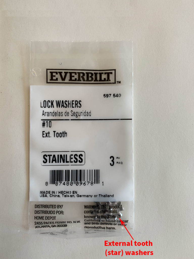
To secure the bracket to the fender, use 3 (per bracket) #10-32 x 1/2″ stainless steel machine screws. Place 3 star/external tooth washers on each screw between the bottom of the bracket and the fender. These will also help make a good electrical connection of the body. Secure the machine screws with 3 #10-32 stainless steel nylon locknuts on the underside of the fender.
5. Mount the Other Bracket on the Passenger Side Fender
Repeat the same process to install the other mounting bracket on the passenger side fender. Measure from the body at the firewall to the right edge of where the bracket should be placed.
You can also use a Kreg KMA2900 multi-mark tool to make sure the depth of the bracket matches the bracket on the driver’s side fender. Measure the bracket on the driver side fender by placing the end of the ruler against the fender. Then note the measurement at the end of the bracket, which is at the 9″ mark in the photo to the right.
Antenna Placement
Time for a little more antenna theory with regards to which antenna is mounted on which side of the Jeep. The Larsen NMO450CHW for the Midland MXT400 is mounted on the passenger side and the Larsen NMO2/70B for the Icom IC-2730A ham radio is mounted on the driver’s side.
Here is why – consider for a moment if both of the antennas were mounted on the back of the Jeep, say on the spare tire carrier as I originally mounted them.
If the antennas are too close together, there is a risk of the transmissions from one antenna being absorbed by the other antenna. Since these radios are capable of transmitting at 40 and 50 watts, if the transmissions from one antenna make it back to the radio connected to the other antenna there is a risk that the radio itself could be damaged by the RF energy. That absorption by the two antennas can impact the overall performance and range of the radios as well.
The idea behind mounting the Larson NMO450CHW on the passenger side is because that is the same side where the factory AM/FM stereo antenna is located on a Jeep TJ. The GMRS frequency band of 462/467 MHz is higher than the FM radio frequency band (~88-108 MHz), so it more or less will have less impact on the FM radio receiver in the Jeep.
The 2-meter ham frequency band of 144-148 MHz is closer to the FM radio frequency band, so putting the Larsen NMO2/70B on the other side (driver) of the Jeep puts it further away from the FM radio antenna. In turn, this (theoretically) reduces the chances of interference.
One thing to note however, given the power that both of these radios operate at it is possible that the FM radio could lose signal while talking on either the GMRS or ham radio. This has not happened to me, but I typically don’t have the FM radio on while either of the GMRS or Ham radios are in use.
6. Install NMO Mounts & Antennas
Now that you understand the “why” behind where each antenna is mounted, let’s move onto the installation.
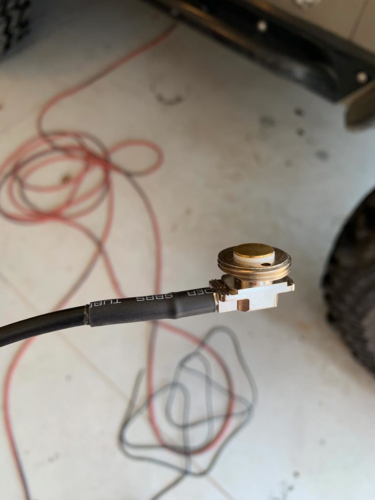
I used Larsen NMOKHFUD NMO 3/4″ mounts which include the coaxial cable and no corrector forth both antennas. An important thing to note is that this type of NMO mount is typically designed to be mounted on the roof of a vehicle where the bottom side of the NMO mount and attached coaxial cable are not exposed to the exterior elements. Just the top/threaded portion of the NMO mount extends above the roofline where the attach is attached.
Given this design, it is important to make sure that the coaxial cable where it enters the NMO mount is properly sealed. If it isn’t, water can make its way inside the sleeve of the coax cable which will cause it to corrode.
Use a piece of marine-grade heat shrink tubing to seal the coax cable at the connector. Harbor Freight sells a good kit of 42 pieces of marine-grade heat shrink for only $5.99. The advantage of marine-grade heat shrink is that it has adhesive on the inside that melts when heated. This creates a good seal to protect against water. Cut a piece long enough to cover the metal connector and a portion of the coax as shown in the photo below. Heat it up with a heat gun until the heat shrink contracts and you can see the adhesive melt on the ends of the tube.
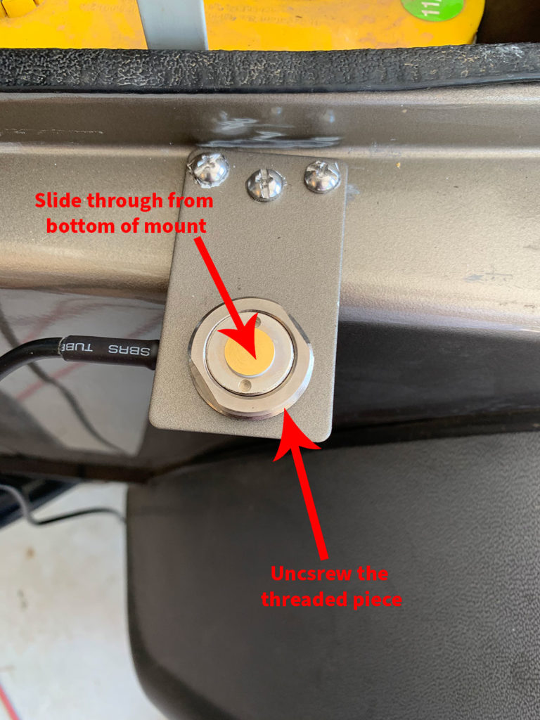
Unscrew the threaded part of the NMO mount and slide the base through the hole in the mounting bracket from the bottom. Re-attach the threaded part and the mount will fit snugly against the bracket. Use an adjustable wrench to tighten the threaded part slowly until it is snug.
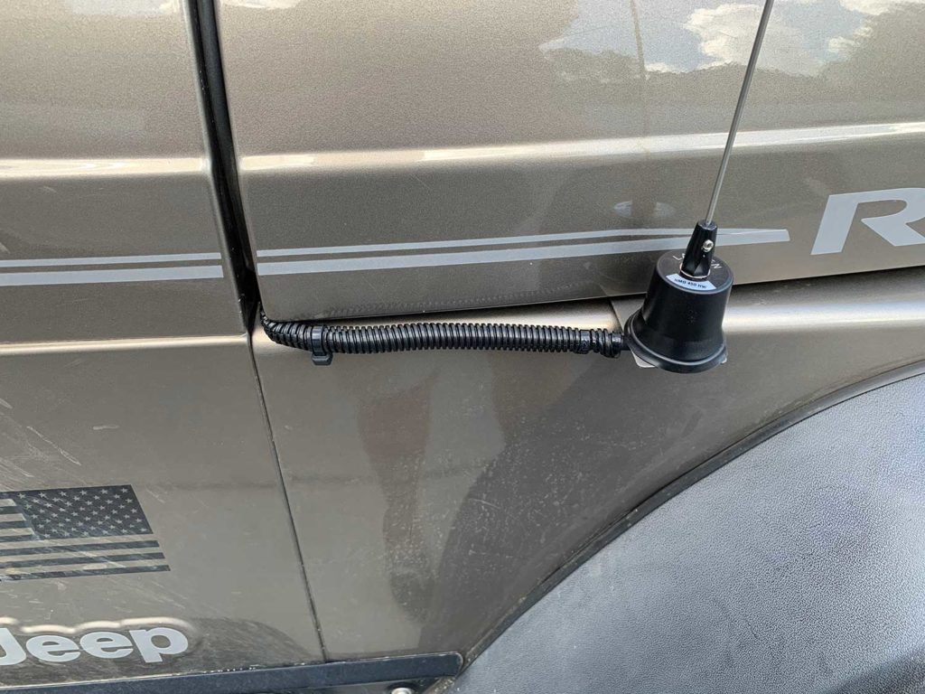
7. Protect the Antenna Coaxial Cable
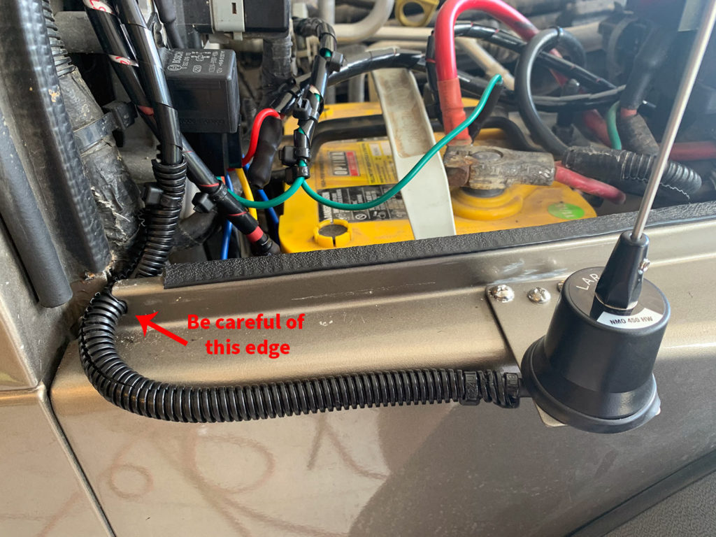
that the arrow is pointing to – it is sharp
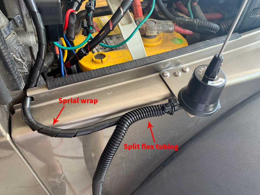
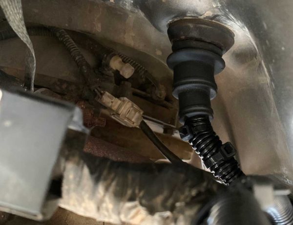
It is important to protect the coaxial cables for both antennas when you route them into the engine compartment. Cover the coax cable with 3/8″ plastic spiral wrap first. Use a zip tie to secure the spiral wrap in place where you start the run. Try and get it as tight as possible so the spiral wrap does not slip. If you have a hard time getting it try, consider using a zip tie puller/cutter tool.
Next, cover the coax cable with plastic split flex tubing and secure it in place with zip ties as well. This will give the coax cable extra protection as the cable needs to be routed around the sharp edge shown in the photo above to the right.
Attach enough split flex tubing so that the cable is protected right past the point where it enters the engine compartment – also see the photo above on the right as well. The edge is sharp and could potentially cut into the coax cable if not properly protected.
I found it was easier to pull the plastic weather stripping that is attached to the body/firewall back, then route the coax cable around the edge then push the weather stripping back into place.
Once you route the coax into the engine compartment do not run it to the point where it will pass through the firewall and into the cab. In part 4 of this series we will install a piece of high temperature braided sleeving that will protect the coax and power cables from high heat since it will be run close to the engine manifold. Just set the coax aside somewhere within the engine compartment where it will not get damaged
Close the hood and make sure it does not create a lot of tension on the coax cable when it is in the closed position. You may need to adjust the turn around the sharp corner to provide a bit more slack if it is tight. When the hood is closed it should look something similar to the photo below.
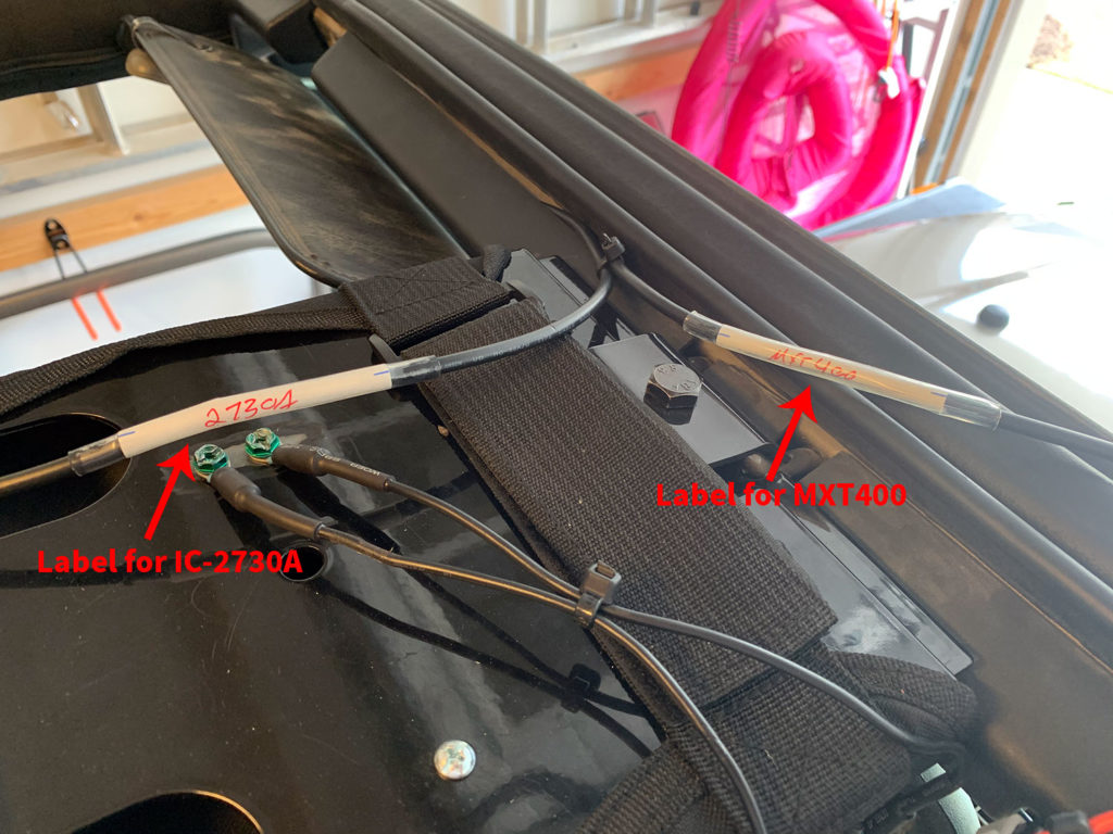
8. Label Both Antenna Coax Cables
IMPORTANT – Label both of the antenna coax cables so you know which cable/antenna goes with which radio. It’s easy to forget this once the coax cables are routed through the firewall and up to where the antennas are mounted.
For the labels, I used regular Avery 06141 file folder labels that you can buy on Amazon or at any office store. These labels have marks on each side, and I aligned those marks with the center of the coax cable (as best I could). Slide a piece of clear heat shrink over the label and heat it up for a nice, weatherproof seal.
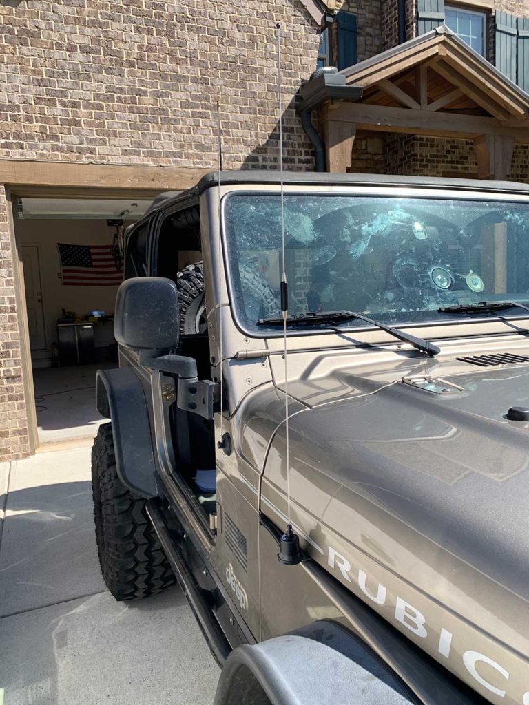
9. Install the Antennas!
Now that the mounts are installed, attach the antennas to the mounts! Both antennas will come with rubber O-rings / gaskets that will protect against water getting in between the antenna base and the NMO mount. Place those O-rings around the mount then screw the antennas to the mounts. For the Larsen NMO450CHW I used the “super seal RGSS gasket” that it comes with. There is a paper insert in the package for the NMO450CHW that explains the difference between the two supplied O-rings.
(Midland MXT400 GRMS Radio)
(Icom IC-2730A Ham Radio)
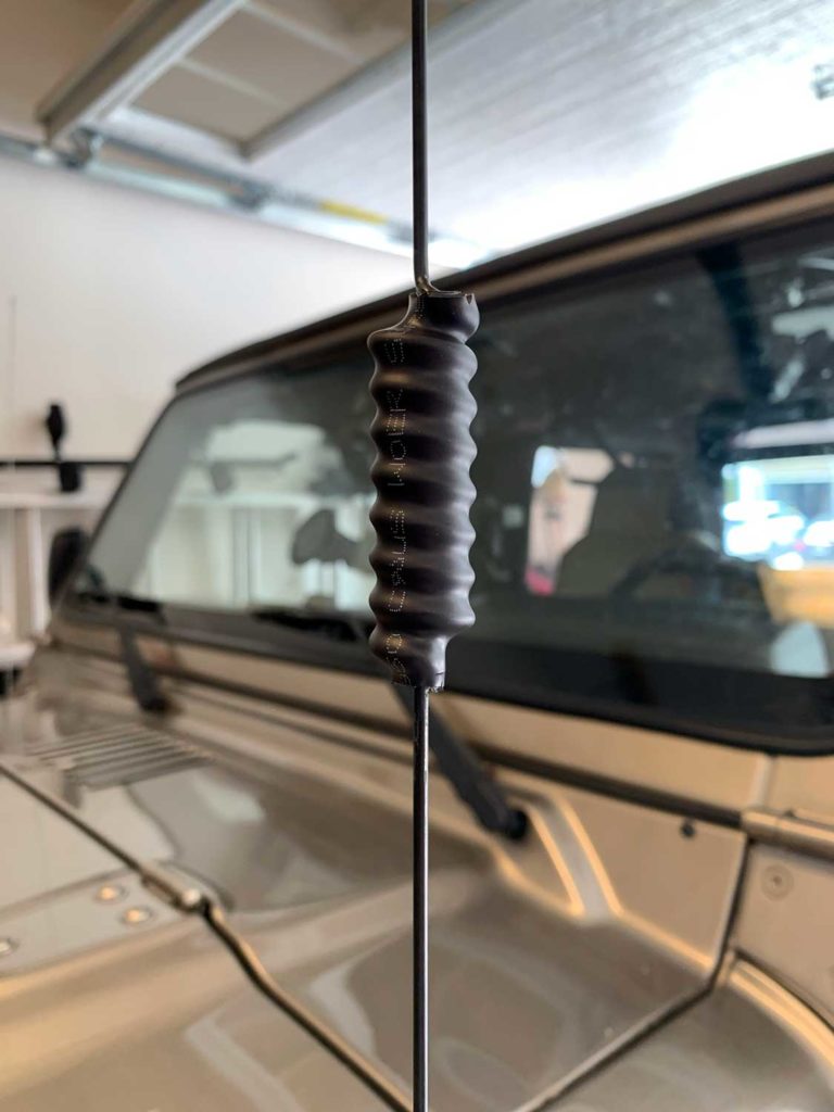
As mentioned back at the beginning of the post in the ‘Reinforce the Antenna Mounting Brackets’ section, the first time I was out on the trail the open coil on the Larsen NMO 2/70B kept getting caught in tree leaves and branches and almost pulled the antenna off of the mount. You can prevent this by covering the coil with a piece of heat shrink as shown in the photo to the right.
I just used a larger piece of the marine heat shrink and trimmed both ends of it once it cooled down.
Up Next – Part 4
Part 4 of this series will cover all things related to power for the radios. Running the power wiring, mounting the fuse blocks and the radio power cables so be sure to check it out next!
No Comments