
Thanks for stopping by Southeast4x4trails.com! If you are looking for a detailed guide on how to install a GMRS radio or Ham radio in your Jeep or off-road vehicle you have come to the right place. Keep reading for more details about this 5-part series on my radio install project.
If you have found your way here via Google, this site is about the Jeep, 4×4, and off-road community in the Southeast US. Check out the home page for an interactive Google map of trails, off-road parks, forest service roads, points of interest and more in the GA, TN, NC, and SC areas. The Journal has other articles similar to this one on topics of interest such as “how-to” guides, trails and places to visit, and local history. The Resources page has many links to mapping, GIS, USFS forest areas, and technical info.
This is the fifth in a series of 5 posts that detail the install of a Midland MXT400 MicroMobile GRMS radio and Icom IC-2730A ham radio in my Jeep Wrangler TJ. You can adapt this information to any vehicle, it doesn’t have to be a Jeep TJ or even a Jeep!
This post will cover the radio RF ground wires, running the radio power cables, running the antenna coaxial cables, attaching the PL-259 connectors to the antenna coaxial cables, and SWR meter testing.
Part 1 includes a complete list of all the radio gear, tools, parts, and hardware that I used.
If you want to jump directly to the install info just click one of the links below:
- Part 1 – Project Details, Gear, Parts and Tools
- Part 2 – Mounting the Midland MXT400 GMRS Radio and Icom IC-2730A Ham Radio
- Part 3 – Mounting the Radio Antennas
- Part 4 – Power, Wiring and Fuse Block Installation
- Part 5 – Radio Power Wiring and Antenna Coaxial Cable Installation
Before we get started I’d like to ask you for a favor. If you find this post useful please consider supporting this site by purchasing any of the items listed in the post through the links provided. The links to Amazon are affiliate links, and the small commission that I may earn keeps this site running so I can continue to provide helpful information.
Parts List
The following parts were used in this post:
■ Midland MXT400 Power Cable (supplied with radio)
■ Icom IC-2730A Power Cable (supplied with radio)
■ RFI RFU-505-ST PL-259 UHF Crimp Style Coaxial Cable Connector (Qty: 2) – Antenna Farm or Ham Radio Outlet
■ Belden 14 Gauge Primary Wire in Red and Black (25-foot roll) – NAPA Auto Parts
■ Tyco Electronics 16-14 Gauge Heat-Shrink Spade & Ring Terminals for #8-#10 Stud – Home Depot
■ Dorman 16-14 Gauge Butt/Crimp Connectors (85436) – Advance Auto
■ Everbilt M4-0.7 X 8MM Phillips Flat Head Screw (574629) – Home Depot
■ Ideal Ground Screws (774042) – Home Depot
■ Storehouse 42 Piece Marine Heat Shrink Tubing – Harbor Freight Tools
■ XHF 160 Piece Clear Heat Shrink Tubing – Amazon
■ Gardner Bender 3.5 Foot Wire Spiral Wrap (FLX-538C10) – Home Depot
■ Littelfuse ATO 15 Amp Smart Glow Fuse (Qty: 2) (0AT0015.VPGLO ) – Amazon
■ Avery 06141 File Folder Labels – Amazon
■ Magnetic Mic Microphone Hanger – Amazon (Optional)
Tool List
The following tools were used in this post:
■ IWISS Ratchet Crimping Tool Set w/ 22-10 Gauge Wire Die – Amazon
■ LP DL-801G Ratchet Crimping Tool for RG58 Coaxial Cable – Ham Radio Outlet
■ Wagner Spraytech Heat Gun – Amazon
■ Wera PH0 Precision Screwdriver – Amazon
■ Dremel Rotary Tool – Amazon
■ Dremel 428 Carbon Steel Wire Brush – Amazon
■ Milwaukee 48-89-4607 Shockwave 5/32” Titanium Drill Bit – Amazon
■ Xacto Black Gripster Knife – Amazon
■ Surecom SW-102 S0239 Digital SWR Meter – Amazon
■ Superbat Male PL-259 to Male PL-259 RG-58 Coaxial Jumper Cable – Amazon (Optional)
Radio System Guide & Wiring Diagram
The graphic below shows the entire radio system and how each component is connected and wired. All parts that are in front of the ‘Jeep Firewall’ box are mounted in the engine compartment. Click to download the diagram in PDF format.
The components that are covered in this post are shown below in red.

1. Wire The Radio RF Grounds
Both radios should be grounded to a bare metal surface. The radio RF grounds make sure that both radios maintain the same RF voltage. This is also known as “bonding”.
To make the radio RF ground wires, cut two pieces of 14 gauge primary wire long enough to reach from the body of each radio up to the top of the overhead console. Strip away enough of the wire shielding to attach a 16-14 gauge ring terminal for a #8-#10 stud and slide a piece of 1/4″ marine heat shrink over the wire before you crimp (attach) the terminal to the wire.
Slide the terminal over the wire and crimp it with a ratcheting crimp tool like the IWISS ratchet crimping toolset with a 22-10 gauge wire die or a fixed-style crimp tool such as the Klien Tools 1000.
Constrict the heat shrink with a heat gun. Attach a ring terminal and piece of marine heat shrink to the other end of the wire as well. Do the same with the second piece of primary wire.
On the Midland MXT400 GMRS radio, there is a pre-drilled hole on the rear of the radio body and in the center of the heat sink fins. This is a perfect place to attach the RF ground wire to the radio. Use an M4-0.7 X 8MM Phillips flat head screw to attach the terminal to the radio body.
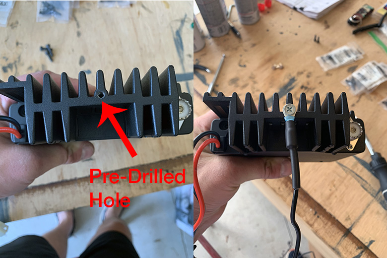
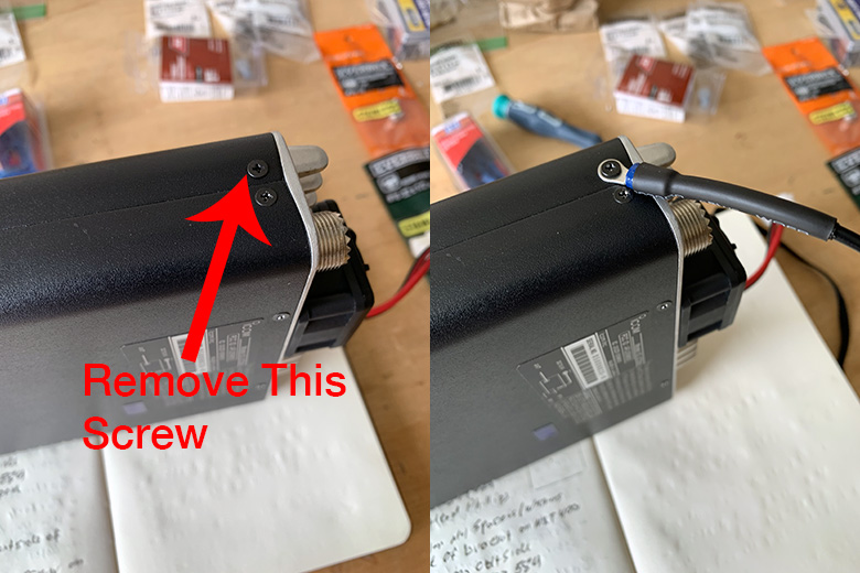
On the Icom IC-2730A ham radio, there is a small screw on the side of the radio body near the rear. Use a PH0 precision screwdriver and slowly turn the screw to remove it. Do not do this quickly or you will risk stripping the screw head because it is so small.
Insert the screw through the ring terminal on the second piece of wire and re-attach it to the radio body.
2. Attach The RF Ground Wires To The Overhead Console
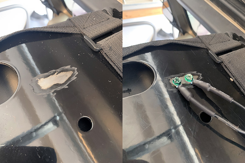
As mentioned above, the ring terminals should make contact with a bare metal surface. Use a Dremel rotary tool and a Dremel carbon steel brush attachment to remove a portion of the coating on the top of the overhead console.
The coating on the overhead console is pretty thick (and durable), so take your time while removing the coating and let the brush do the work. You only need to remove enough of the coating so that the area is large enough to screw both of the ring terminals to the overhead console.
Test fit the terminals and use a marker to make a dot in the center of each ring terminal. Drill two pilot holes with a 5/32″ metal drill bit.
Clean the area to make sure it is free of any residue from the console coating and drill shavings. Secure the ring terminals against the overhead console with two Ideal ground screws. These ground screws are a #10-32 in size. Gather the wires together and secure them with a zip tie as well.
3. Route the Radio Power Cables
Both the Midland MXT400 and Icom IC-2730A come with DC power cables. Both of these cables are routed from the 6-circuit distribution fuse block under the passenger seat to the radios where they mounted on the overhead console.
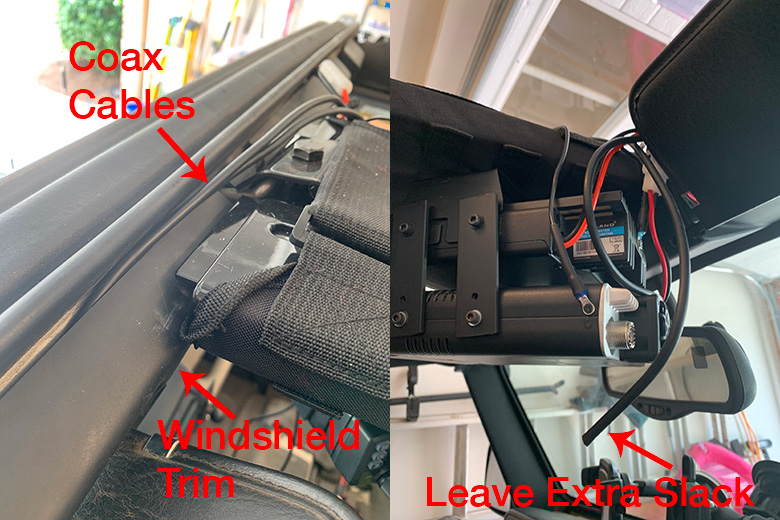
Before you start routing the wires remove the plastic trim that is around the windshield. The power cables will be hidden by these trim pieces.
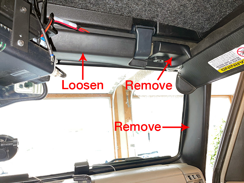
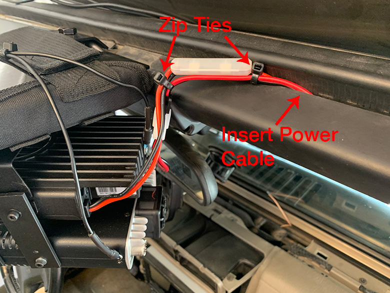
Attach each power cable to its connector on the radio body. Gently pull the plastic trim piece back that runs along the top of the windshield and insert each cable between the windshield frame and the trim piece – one cable at a time.
I zipped tied the power cables together once they were inserted between the trim piece and the windshield frame to keep them together. The plastic trim piece will not sit completely flush against the windshield once it is re-tightened, as the power cable wires will stick out of it at the top.
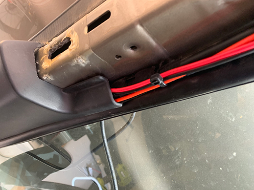
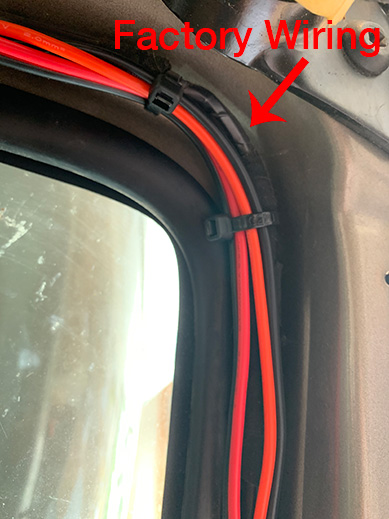
On the passenger side of the Jeep, route the power cables along the top of the windshield and then down the side of the windshield, behind the dashboard, and to the floor of the Jeep. I used zip ties to secure the cables to the existing factory wiring as shown in the photo below on the right below.
Since the floor of the Jeep does get hot, it is a good idea to cover the power cables in plastic spiral wrap for protection. Start the spiral wrap where the cable touches the floor and run it along the length of the cable to where it will connect to the distribution fuse block underneath the passenger seat.
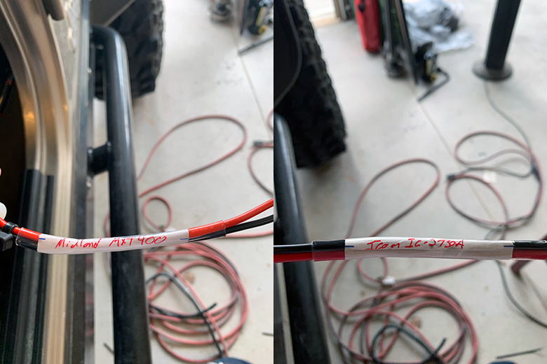
It is easy to forget which power cable attaches to which radio, so it is also a good idea to label both cables for easy identification. Use an Avery 06141 file folder label on each wire and cover it with a piece of clear heat shrink. I placed the labels at a point on the cables that is near where the cables connect to the distribution fuse block.
4. Extend The Power Cable For the Midland MXT400
The power cable for the Icom IC-2730A was long enough to reach from the radio to the distribution fuse block. The power cable for the Midland MXT400 was not, however.
Extending the power cable is straightforward. Cut two lengths of 14 gauge primary wire that are long enough to run from where the MXT400 power cable stops to the distribution fuse block. Leave some extra slack in case you need to re-terminate the connectors on the cables in the future. Match red primary wire to the red wire on the MXT400 power cable, and black to black.
Cut two pieces of marine heat shrink and crimp a 16-14 gauge ring terminal for a #8-#10 stud on each piece of wire (on the end of the extension wires – where it will connect with the distribution fuse block). Crimp the extension wires to the MXT400 power cable with two 16-14 gauge butt connectors and two pieces of marine heat shrink.
Cover the MXT400 power cable and the extension wires in plastic spiral wrap where they make contact with the floor of the Jeep as you did for the Icom IC-2730A power cable.
5. Attach The Power Cables To The Distribution Fuse Block
Remove the Phillips head screws for 2 positive terminals and 2 negative terminals on the distribution fuse block. If you are looking at the fuse block as shown in the photo below, the two positive terminals are those that have slots for the 15A fuses, and the negative terminals are those that do not have slots for the fuses.
I attached the power cable for the Icom IC-2730A to the terminals on the right side of the fuse block, and the power cable for the Midland MXT400 on the left side of the fuse block (as shown by the labels on each power cable).
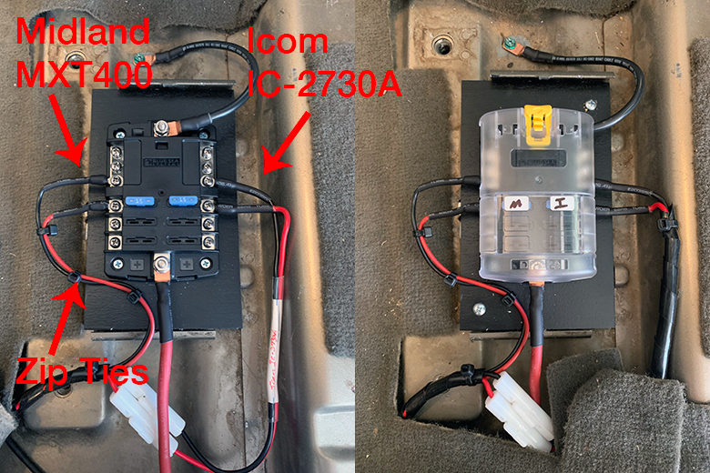
Zip tie the power cable extension wires together for the MXT400. Insert two 15A fuses into the slots for each power cable. I also used the labels that are included with the Blue Sea Systems distribution fuse block and put them on the fuse block cover. ‘M’ is for the Midland MXT400 and “I” is for the Icom IC-2730A.
NOTE: Both of the radio power cables have 15A in-line fuses installed from the factory. Theoretically, you don’t need 2 sets of fuses (one in-line and one on the distribution fuse block). You could remove the inline fuse holders and use 16-14 gauge butt connectors to connect the power cable wires together, but I decided to leave them in place in case I ever removed the power cables and wanted to use them in another vehicle in the future.
Just keep in mind that if a fuse does blow, be sure to check both the in-line fuse and the fuse in the distribution fuse block. If you do choose to remove the in-line fuse holders, use a piece of marine heat shrink to cover each butt connector to protect it against water.
6. Route The Antenna Coaxial Cable
Routing the antenna coax cable is pretty much the same as routing the radio power cables. Route the coax cable behind the plastic windshield trim and secure it in place with zip ties.
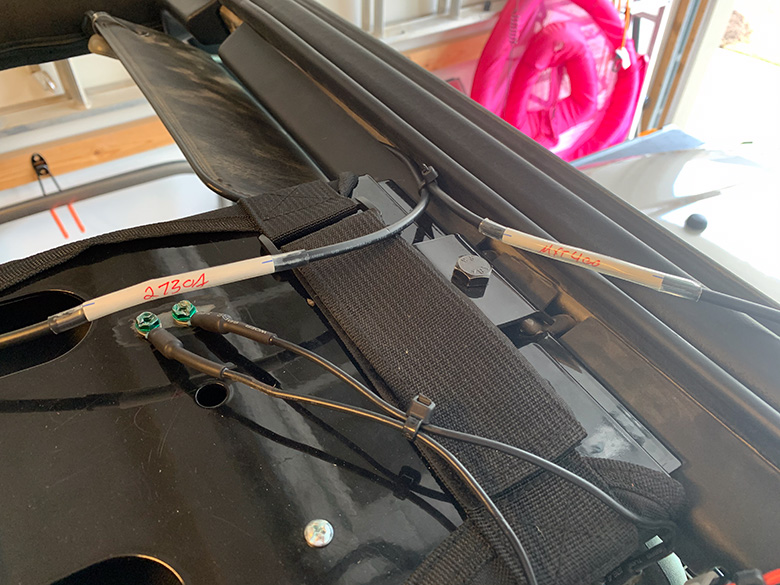
The coax cable for the Midland MXT400 is routed on the passenger side (the antenna for the MXT400 is mounted on the passenger side fender), and the coax cable for the Icom IC-2730A is routed on the driver side of the windshield (the antenna is mounted on the driver side fender). Pass both coax cables out of the plastic windshield trim at the top just as you did with the power cables.
Determine how much length is needed for the coax cable to reach the antenna output connectors on the radio bodies. Keep in mind you will still need to attach the PL-259 connectors to the end of the coax cable. It’s best to leave extra slack and trim it down if needed. This also gives you enough coax cable to re-terminate (install new connectors) if needed in the future as well.
While some extra slack is not an issue, the coax cables should only be as long as they need to be to reach the antenna output connectors on radio bodies. Coiling up the excess coax cable and not cutting it to length is a bad idea and it will impact the overall radio/antenna performance and SWR measurements.
The antenna output connector is on the left side of the Icom IC-2730A radio body and the right side of the Midland MXT400 radio body (if you are looking at the radio body from the rear).
Label both of the coax cables as well so it is easy to identify which cable goes to which antenna.
7. Attach The PL-259 Connectors
This was one of the most difficult steps of the install for me. Mainly that is because I had never installed connectors onto a piece of coax cable before. If it is your first time installing connectors as well, these are a couple of tips that I would suggest:
- Order EXTRA PL-259 connectors and use them to practice the installation first
- Use a piece of the excess coax cable that you cut when trimming in step 6 (or buy a few feet of extra cable) to practice
- I ended up making a short jumper coax cable with my practice installations – you can use this jumper cable in step 8 for the SWR meter testing. I used a length of coax cable that was about 12″ and installed two of the extra PL-259 connectors onto each end
- You can buy a special tool for stripping RG-58 coax cable. I bought one and it ended up cutting too deep and through most of the braided shielding on the coax cable. The depth of the cut is usually adjustable, but I didn’t want to go through the process of adjusting/cutting so I just used a sharp Xacto knife and made multiple, shallow cuts on the coax cable until it was properly stripped.
- Use the crimp style PL-259 connectors. There is debate over the quality of the connection on a solder vs. crimp style connector, but the crimp style connector is far easier to install and is perfectly suitable for this application (and is used in many professional radio gear installations as well).
- Use a ratcheting crimping tool to install the PL-259 connectors
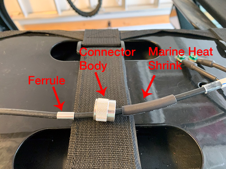
You will need two PL-259 connectors and the ratcheting crimping tool mentioned above. I used the RFI RFU-505-ST connectors and the LP DL-801G ratchet crimping tool for RG-58 coax cable/connectors.
Before you strip the coax cable, slide the PL-259 connector ferrule and connector body over the coax. Also cut a piece of marine heat shrink and slide it down the coax cable as well. The order for each piece is marine heat shrink (covers the ferrule once crimped) > ferrule > connector body. Do this for both coax cables.
Next, manually strip enough of the coax cable to install the connector. Be CAREFUL when stripping – if you make several errors while stripping and have to cut the coax cable and start there is a chance of it becoming too short to reach the antenna connector output on the radio body. If this happens you will have to remove, replace and re-run the coax cable all the way from the antenna mounting brackets that are on the fender of the Jeep – this is A LOT of work to undo and redo.
You can use the top of the overhead console as a solid workspace while stripping the coax cables as well.
I watched many videos on YouTube on how to install the PL-259 connectors. You can find them by searching the term ‘how to crimp PL-259 connectors‘. The type of coax used in this project is RG-58.
The die size to use on the ratchet crimping tool is .213 for the connector ferrule and .069 for the center conductor wire.
This is one of the better videos that I watched and used it primarily to learn how to do the installation. It’s much easier to watch someone do it than to try and learn from just photos. Remember, PRACTICE FIRST before you install the connectors on the “real” coax cables for the radio antennas!
Once the connectors are installed, screw them onto the antenna connector outputs on the radio bodies and make sure they are snug.
Reinstall the plastic windshield shield trim pieces and your install is COMPLETE!!!
8. SWR Meter Testing
A SWR meter, or “standing wave ratio” (also known as a VSWR meter – voltage standing wave ratio) is used to test the SWR ratio of a transmission line (the antenna coax cable). This is the ratio of how much of the output power from the radio is being delivered to the antenna and how much power is reflected by the antenna and back to the radio.
Measuring SWR is important for two reasons. First, if too much power is being reflected by the antenna back to the radio it can cause significant damage to the radio depending on how high the SWR ratio is. Second, it is a tool that can be used to tune the antenna for optimal signal transmission and performance.
An SWR reading of 2.0 or numerically lower is generally considered safe to operate without the worry of radio damage. Any SWR reading numerically higher than 2.0 is considered increasingly unsafe and you risk the potential of damage. An SWR reading of 3.0 or higher means you will damage the radio if you are transmitting for an extended amount of time.
The “ideal” SWR reading is in the 1.0 to 1.5 range.
I used the Surecom SW-102 S0239 Digital SWR Meter and an RG-58 coaxial cable jumper of about 12″ that I made with the excess coax cable and male PL-259 connectors while practicing the connector installation (as mentioned above in step 7). You can also purchase pre-made coax jumper cables as well.
The SWR meter has to female PL-259 connectors on each side. Attach the coax jumper cable to the antenna output on either radio and the other end of the jumper cable to the input on the left side of the meter labeled TX. Attach the coax cable that runs to the antenna to the connector on the right side of the meter labeled ANT.

Make sure you are in an open area such as an empty parking lot and at least 20 feet away from any buildings, structures, vehicles, or metal objects. If they are closer than 20 feet it can affect the signal being transmitted to the antenna and in turn, the SWR meter reading could be inaccurate.
On the Surcom SW-102 SWR Meter, press and hold the red button to power the meter on. Once it is on, by default it is set up to take the SWR reading when you key the radio microphone to transmit.
Typical advice when testing SWR for an amateur radio (or GMRS for the Midland MXT400) is to start at the bottom of the band and take a reading, tune to the middle of the band and take a reading, then tune to the top of the band and take the third reading. This allows you to measure the average SWR reading across the entire band.
So, on the Icom IC-2730A ham radio on the 2-meter band that would be 144 Mhz on the low end of the band, about 146 Mhz in the middle of the band, and 148 MHz on the upper end of the band. For the 70-cm band that would be 420 Mhz, 440 Mhz, and 450 Mhz, respectively.
On the Midland MXT400 GMRS radio, you could take readings at the 462 MHz portion of the band (channels 1-7), 467 Mhz portion of the band (channels 8-14), and then again at 462 MHz but at higher GMRS power (channels 15-22). See this frequency chart for the specific frequencies for each channel and allowed output power.
These frequencies are approximations and don’t have to be exact, so make sure the frequency is clear before you transmit.
When you key the microphone to transmit, the SWR reading will display on the meter. It also measures the actual output power as well.
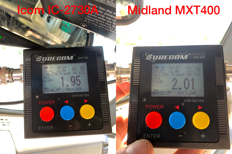
These are photos of the actual SWR readings I took after I finished the install. On the left, you can see that the SWR reading was 1.95 on 146.010 MHz at an output power of 46.4W (not quite the 50-watt max output power) for the Icom IC-2730A.
On the right, the SWR for the Midland MXT400 was 2.01 on 462.550 MHz at 32.3 watts (also not quite the max output power of 40 watts).
Depending on the SWR readings that you get, you can determine if additional antenna or system tuning is needed. I did not take any further steps to tune the antennas based on these two readings, but I may do so in the future.
If you are interested in learning more about how to tune the antennas, read post #50 in the original RadioReference.com forum post about this installation projects.
These articles and video also provide some additional information about SWR testing, interpreting the readings and antenna tuning:
- How to Use A SWR Meter To Test Antenna Standing Wave Ratio (SWR)
- What is SWR And Why Is It So Important?
- Rugged Radios Tech Tip: How To Use An SWR Meter (Video)
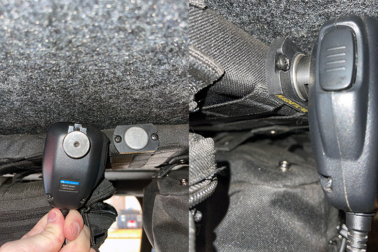
9. Magnetic Mic Microphone Hanger
This is completely optional, but I did find it to be very helpful while on the trail. The Magnetic Mic microphone hanger replaces the hanger that is supplied with the radio. It isn’t compatible with the Icom IC-2730A mic, but it does work with the Midland MXT400 mic. Most of the people I ride with use GRMS radios on the trail, so the mic for the MXT400 is the one that I take on and off its hanger all day.
The Magnetic Mic hanger is exactly what it sounds like. It has a strong magnetic base and another magnet that attaches the circular piece on the back of the MXT400 mic. Since the magnet is very strong, all you have to do is get the mic in the general area of the hanger base and it will snap to it. Very handy while bouncing up and down on the trails.
Wrapping Up
Congratulations on completing this installation project. It is far more work than your average ham or GMRS radio install. You can rest easy knowing that your radio system is made up of top quality gear and is installed the right way. I think you will be pleased with the radio system’s performance.
Feel free to reach out to me with any questions that you might have and I will do my best to help. You can reach me via e-mail from the About page or on Facebook at Southeast4x4Trails.com.
2 Comments
Ken
January 28, 2021 at 4:27 amWow Colby,
I am very impressed. How long did that take you? I am glad I came across this by chance. I am putting in a Midland MXT400 GMRS radio and a BearTracker 885 Hybrid CB Radio/Digital Scanner in my jeep starting this weekend i hope. Because of you though i have lost 2 hours of sleep and about $200 poorer tonight lol. But, I thank you. I am going to get the Smittybilt G.E.A.R. Overhead Console in the next day or two. I have already purchase a CB radio hanger that fits above my mirror. So, i am going to go to Ace and get longer 25mm hex screws to fit both the console and CB radio hanger. I’m thinking and hoping the 2 will work good together, and I had more storage! It looks like your rear view mirror might partially be blocked? My radios will be at about the same height.
When you were grounding the radios, if you scraped paint off under where the mounting screws fit, wouldn’t that be a sufficient or good ground since everything is bolted to the console which is bolted to the body?
Colby
January 28, 2021 at 11:15 amHey Ken,
Thanks for the comment! I’m glad the posts are helpful – they should save you some time to re-gain the lost sleep!
On the install time, it took me about 7 full days to do it all. I took a week off of work in July last year to do most of it, but that time also includes troubleshooting when things didn’t work, going back and forth to a bunch of stores, and having to re-do the portion of the install for the Lind shut-down timer. Outside of the actual install work I spent well over 40 hours on planning the project between the RadioReference.com forums, researching and buying all of the parts.
The additional storage on the overhead console is nice. I usually keep items that would otherwise roll around on the seats or storage compartments in there. Also, items that I want quick access to. The rear view-mirror is partially blocked, but it doesn’t really make that much difference because my spare tire was already blocking a portion of the view. I can still see the thermometer on the rearview mirror if I lean forward a little bit.
As for the grounding, you could do that as well. I wanted to make sure I had a bare-metal to bare-metal contact, so I grounded them on top of the overhead console. The coating on the console is rather thick and a plastic-like or PVC material, so you wouldn’t want to ground them to it without removing the coating first. As long as the crimp terminal touches bare metal you will be good to go.
I also did a somewhat similar install for my Uniden SDS100 scanner too last year, but I haven’t had a chance to do a post on that project yet. I have a COMPACtenna SCAN-III antenna mounted on the rear tire carrier with a run of LMR-400 coax that runs up to the scanner which is mounted on the windshield.
Feel free to ask any other questions. Happy to help. If you do pick up any of the items from the post that are on Amazon please consider using the links in the posts (they are affiliate links). The small amount of commission from them helps keep the site running (thanks in advance if you do).